Introduction
Over the years I have built quite a few projects, some from magazines such as Everyday Electronics, Practical Electronics and Electronics Today International (ETI) and others
I've designed myself. I have covered some in the Old Meters & Test Equipment page but there are some that don't fit into that catagory so I've introduced this page to cover
these projects. As I unearth my old project files I'll add them to this page in chronological order, the first one is a TV Sound Separator..
Fuzz Box - 1975
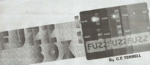 The Fuzz Box was my very first project, I'd bought a copy of Everyday Electronics and it looked like a project I could build. At only £3.00 I could afford it so I went to my local Electronics
shops, RME and Bothwell Electrics to buy the parts. It was a steep learning curve as I'd never worked with strip board let alone transistors! needless to say it didn't work first time but I got it going
in the end. In hindsight I think it helped me get my first job as a Trainee Electronics Technician as I could speak confidently, if not laughingly, about my experiences.
TV Sound Separator - 1975
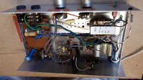
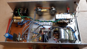
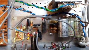
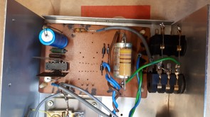
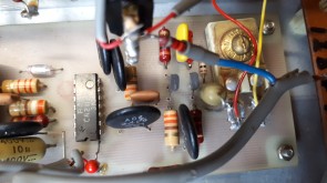
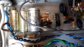
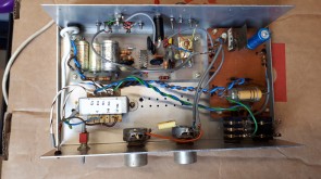
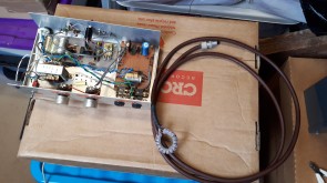
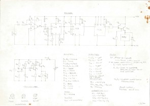
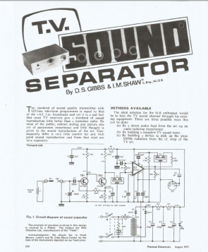 Back in the 1970's TV sets generally didn't have any audio or video connections, there was no way to get audio or composite video out for recording. This TV Sound Separator picks up the stray RF
at the rear of the TV then decodes it allowing you to either record the sound or use headphones. I used it to record programs such as Top of the Pops and The Old Grey Whistle Test on my cassette recorder.
Back in the 1970's TV sets generally didn't have any audio or video connections, there was no way to get audio or composite video out for recording. This TV Sound Separator picks up the stray RF
at the rear of the TV then decodes it allowing you to either record the sound or use headphones. I used it to record programs such as Top of the Pops and The Old Grey Whistle Test on my cassette recorder.The design was published in the August 1975 Practical Electronics magazine and I supplemented it with a headphone amplifer. The system worked well for some years until TV manufacturers started to screen the RF portion of the PCB and introduced Headphone sockets thus making this unit redundant.
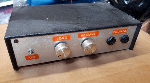
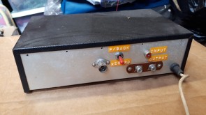
This is one of the few bits of kit that I have kept all the way from 1975!
7 Watt Stereo Amplifier - 1976
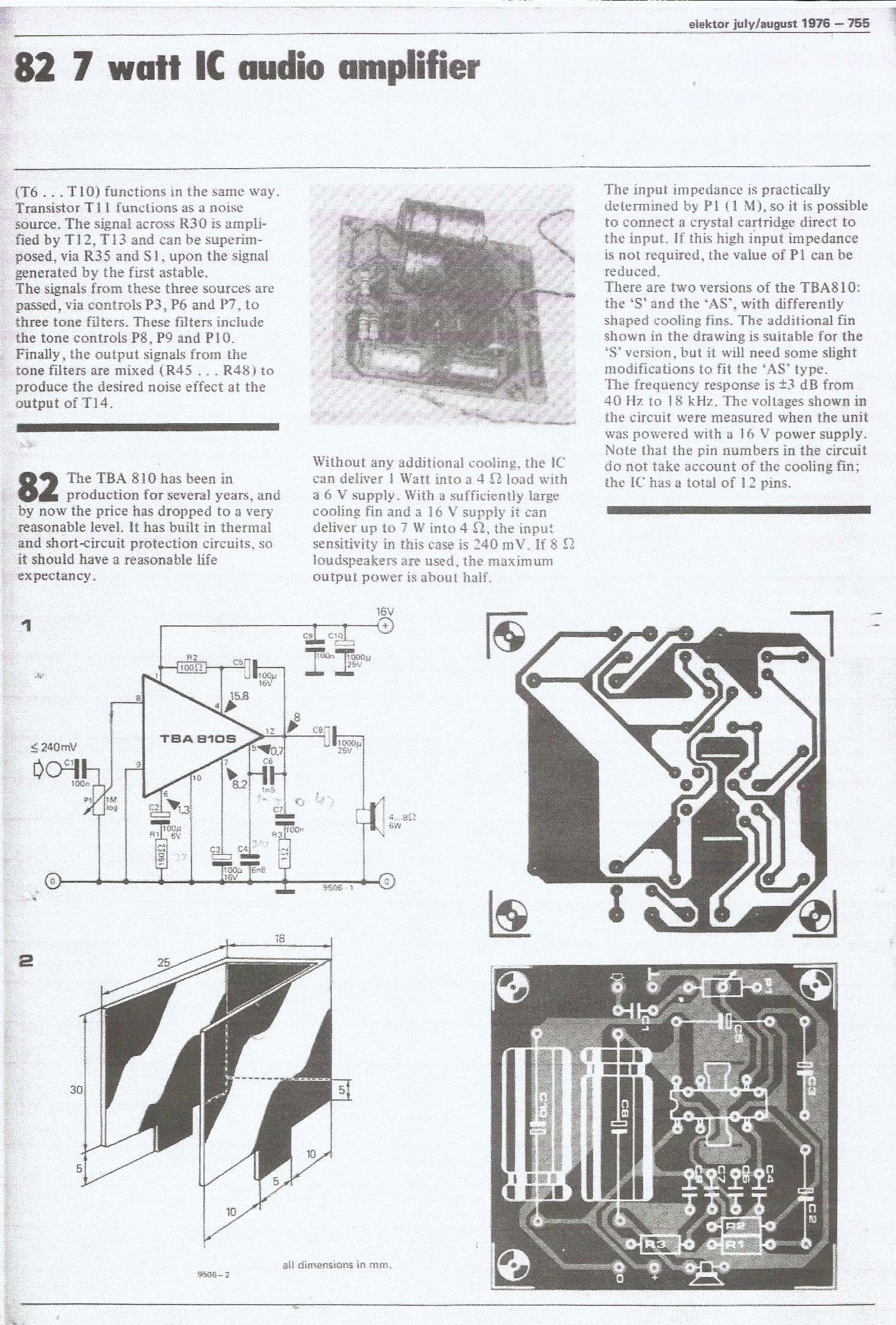
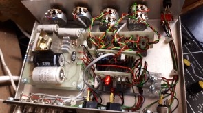
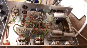
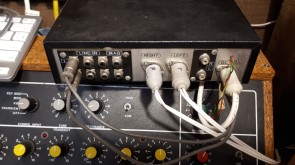
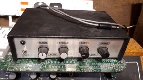 This 7 watt stereo amplifier which I still use today is based on the Elektor project No.82 in the July/August 1976 magazine. To turn it into a more versatile amplifier I added a Magnetic cartridge pre-amp,
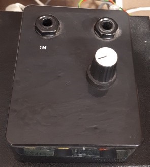
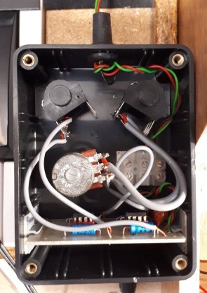
tone controls and instead of an input selection switch a four channel mixer. I also added line out terminals and later a bit of a fudge of a headphone amplifier - no room inside the case!

Variable PSU's - 1976
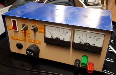 I adapted a design from ETI project 111 Jan 1973 to make it into a 0-30V/1.5A supply and added volt/current meters along with range switches for easier control. I bought surplus meters
from a local shop (Marshalls) and recalibrated them, I also put on new scaling by turning over the existing scale and labelled it using Letraset.
![]() ETI111 Power Supply.
ETI111 Power Supply.
![]() ETI111 - My workings.
ETI111 - My workings.
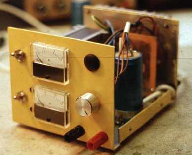
I later built this one with a higher current rating 0-30V/3A. I was using it at work and unfortunately it went missing from my desk..I hope it went to a good home!
Touch Switch Darkroom Photographic Timer - 1977
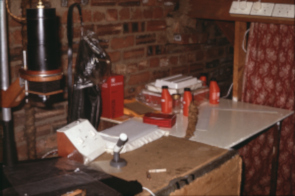
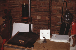
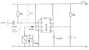 While I worked as an Electronic Technician I managed to barter a darkroom Enlarger from a colleague, this was a much needed upgrade from my homemade one so to complete it I decided to build a touch switch
darkroom timer. Prior to this timing exposure was by watch and a flick of a switch but this timer made it so easy to control - select time and touch switch..done..and so repeatable. The circuit
is a simple 555 timer with switch selectable timing resistors and an output relay to switch the enlarger bulb.
Ni-CAD Charger - 1979
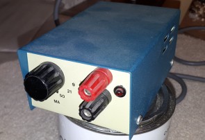
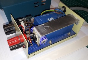
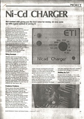
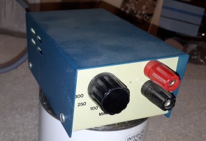 Ni-CAD chargers were all the rage in the 70's, they appeared in every magazine of the day. I chose to build the charger that was published in the August 1979 issue of ETI but of course I modified it to
suit me - I reduced the number and value of charge currents.
Logic Probe - 1979
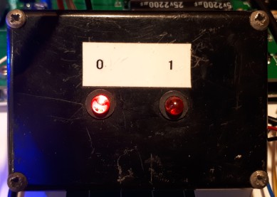
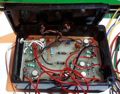 When I needed a logic probe I looked back at old ETI projects and came across the ETI120 article. It was such a great little probe I built two and I'm still using them today when testing my Electron
Sequencer board. I've even seen one built into a Tic Tak box using 7 segement displays to indicate a 1 or 0!
![]() ETI120 Logic Probe article.
ETI120 Logic Probe article.
8 bit Sequencer for Maplin 3800 Synthesiser - 1980
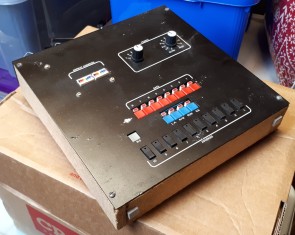 After building the Maplin 3800 Synthesiser I looked at the Maplin 600 note sequencer but at £125 + it was way too expensive so I thought I'd have a go at designing and building my own and this is the
result. It worked very well but lacked the very useful feature of being able to load and save sequences so I had to write down any that I liked and then re-type them in when needed - very labourious.
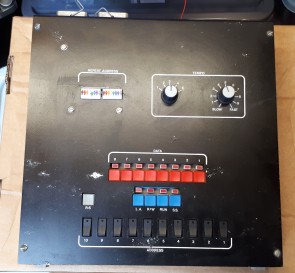
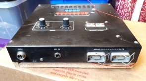
How it worked was very simple - press reset, press the R/W to write, set the data to the note required then single step it onto the next address. Once the sequence is complete set the repeat address
to the last address, set R/W to Read then press run to start the sequence. Tempo is set by the rotary switch and the potentiomenter.
At the start of the 1980's I didn't use Micro Controllers or Processors so the design was based round 74 series logic, Static RAM and of course a 555 timmer. The following is my entire project file
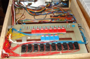
including circuit diagrams , pcb's, case and the synth interface along with a few photos. During this period there was no CAD so the PCB tracking had to be designed onto clear acetate using track & pad
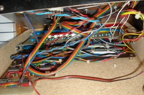
transfers which is then used to photo etch the board. I thought it would be a very complicated design to manually place each track so I made a board with pads for each IC so the IC's can be soldered
in place then all the pin connections could be done using wire.
![]() Sequencer Circuit Diagrams.
Sequencer Circuit Diagrams.
![]() Sequencer PCB layouts.
Sequencer PCB layouts.
![]() Sequencer Block Schematic.
Sequencer Block Schematic.
![]() Sequencer Case.
Sequencer Case.
![]() Sequencer/Synthesiser Interface.
Sequencer/Synthesiser Interface.
![]() uPD2114L Static RAM data sheet.
uPD2114L Static RAM data sheet.
![]() MM2111 Static RAM data sheet.
MM2111 Static RAM data sheet.
In 1984 I revisited the Sequencer to increase it from 8 bit to 16 bit with double the memory. Unfortunately I never got round to building it.
![]() 16 bit Sequencer Circuit Diagrams.
16 bit Sequencer Circuit Diagrams.
![]() HM6116L Data Sheet.
HM6116L Data Sheet.
Ultrasonic and Infrared remote Controls - 1980, 1984 & 1986
Ultrasonic
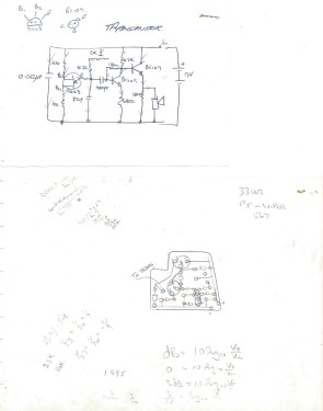
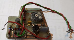 This is all that has survived of my Ultrasonic remote control, the handset electronics minus the transducer! During the late 70's and early 80's there was a keen interest in ultrasonic control
in the electronics magazines, they all had projects of one description or another. I built this one to switch on and off my TV..yes TV didn't have remote controls! I think this design came from a magazine
but I can't remember which one although I probably modified the reciever to switch the mains suppy. Here are my circuit diagrams and PCB layout..note the obvious error - I etched the track on the
wrong side of the PCB!
Infrared Mk1
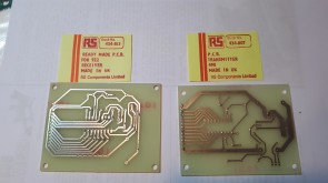
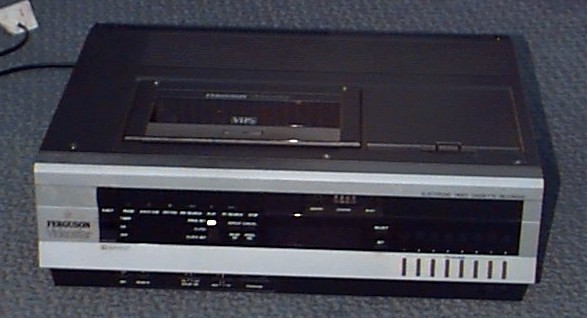 My first look at Infrared Remote Controls was when I wanted to replace the wired remote control on my Feguson Videostar 3V30 video cassette recorder. I used the RS components datasheets to select
the basic circuits I needed, I even bought their circuit boards, but I had to make some additions to the circuit to accommodate a pseudo Feguson remote control so didn't use them in the end. I added a
BCD decoder and some 'd' type flip flops to toggle relays which swiched in resistors to emulate the wired remote control. On striping down the existing control and reverse engineering it was possible to
see how it worked and luckily is was a simple resistor ladder which was easy to simulate.
My first IR Remote Control system then consisted of a transmitter handset which sends pre-selected codes to the receiver unit, the receiver then decoded the message and switched the appropiate relay
and hense the function. The receiver unit consisted of a Power Supply, a receiver amplifier and a decoder board and sat snuggly at the side of the Video machine. The following documentation includes the
circuit diagrams and PCB layouts and all my workings.
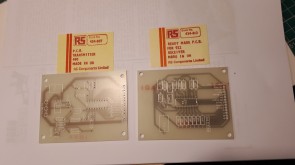
![]() My Mk1 Ferguson Videostar 3V30 Video IR Remote Control designs.
My Mk1 Ferguson Videostar 3V30 Video IR Remote Control designs.
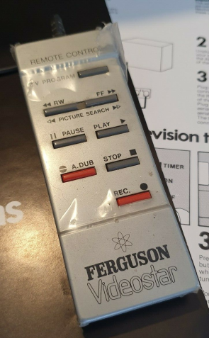
The wired remote control whose wire was not long enough to reach the couch!
Infrared Mk2
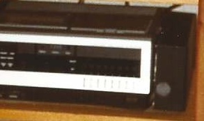 In 1986 I decided to upgrade the Infrared Remote Control to provide new features such as silent operation - no relays, voltage controlled amplifer for volume control and a smaller controller. Again I've
not a lot left of the original transmitter and receiver but I have the original keyboard circuit boards and an unused part built receiver PCB. All this was superceded a few years later when both TV's and
video recorders came with their own remote controls.
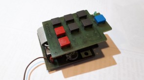
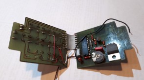
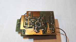
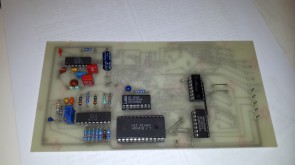
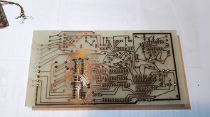
![]() My Mk2 Ferguson Videostar 3V30 Video IR Remote Control designs.
My Mk2 Ferguson Videostar 3V30 Video IR Remote Control designs.
![]() RS Datasheet Remote Control IC's 3560 July 1983
RS Datasheet Remote Control IC's 3560 July 1983
![]() RS Datasheet Remote Control IC's 3560 July 1984
RS Datasheet Remote Control IC's 3560 July 1984
![]() RS Datasheet Remote Control IC's 3560 July 1985
RS Datasheet Remote Control IC's 3560 July 1985
![]() RS Datasheet Remote Control IC's 7786 July 1987
RS Datasheet Remote Control IC's 7786 July 1987
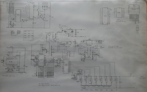
Autoranging Frequency Meter - 1983
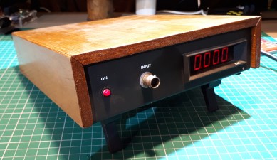
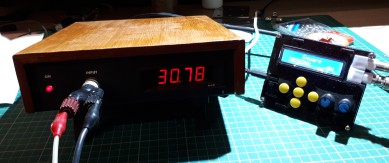
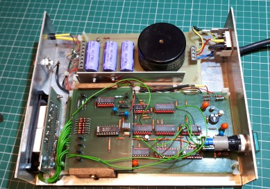 A piece of test gear I didn't have at his time was a frequency meter and when this one appeared in Wireless World I thought I'd build it.. and it still works well.
![]() The Wireless World 1983 Autoranging Frequency Meter article and my build notes.
The Wireless World 1983 Autoranging Frequency Meter article and my build notes.
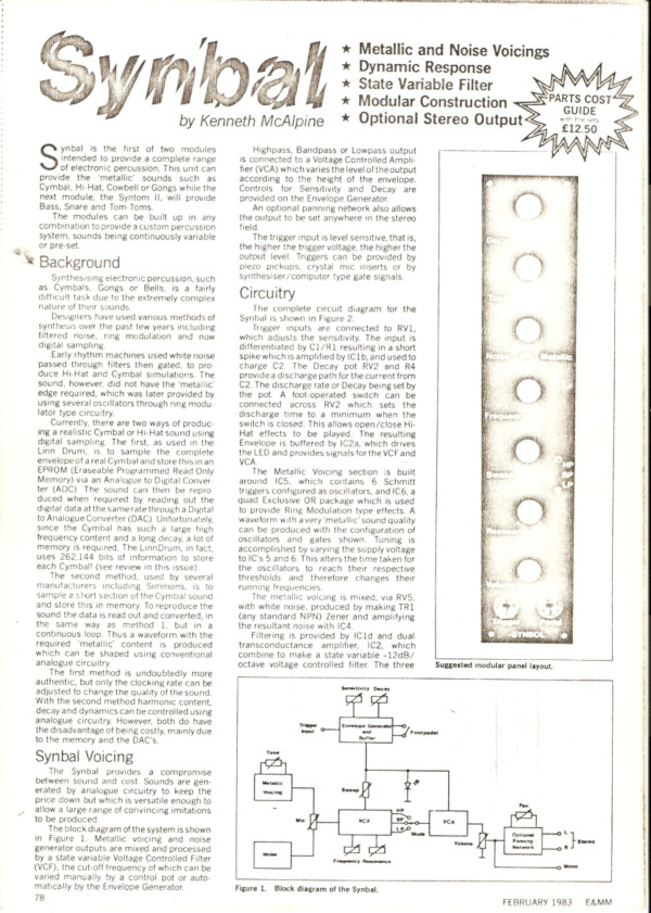
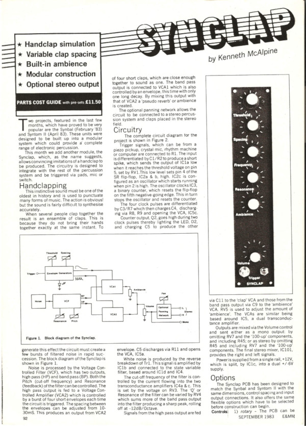
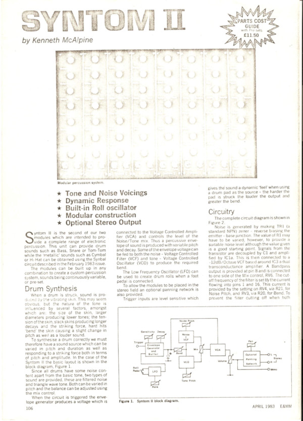
E&MM Synbal, Syntom II and Synclap - 1983
Having built the Maplin 3800 Synthesiser I wanted to build some drum effects and the Syn projects were just being published at that time. I ordered one of each board then used them as
templates to make a few more of each PCB. At that point the project came to a halt and was just revisited and completed in 2015.
I had left the project in a bit of a mess with some completed boards, some part built but none assembled into a decent rack. I had enough PCB's to build four SynTom II's,
four SynBal's and a SynClap. They are all now built and assembled in a rack and controlled via a Raspberry Pi sequencer. Now in 2020 I'm replacing the Raspberry Pi with a sequencer built
using an Acorn Electron computer - there is another page on the site that charts my progress with that project.
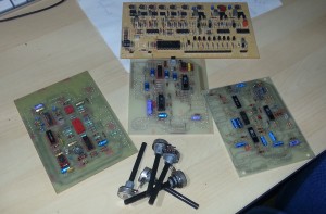
Some of the boards as they were left in 1983/4.
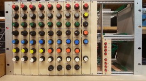
The completed drum rack. There is a short video of the rack in action on the Raspberry Pi pages.
Clock/Timer for HI-FI recording - 1985
 During the 80's I had a Sony TC-FX2 cassette deck which had the facility to set the record feature with the power off then when power was restored it engaged the heads to start the recording. To
let me use this function I designed a clock which could store On and Off times. These times were then used to switch the mains supply to activate the recording. The clock had an LCD display,
some LED's and all the buttons necessay to set the time, the on/off times and an override. The clock circuit was built using CMOS integrated circuits, 74HC and MM45 series all on a matrix
board with wire wrapped point-to-point wiring. To finish it off it was built into a nice brushed aluminium case to match the recorder. Unfortunately it was dismantled many years ago and I don't have
any photos.
To put some context round why I did this and not just buy a mains timer unit is that in the 80's these timers used mechanical mechanisms which would randomly switch on or off within roughly a 10 minute
window - not good when you wanted to catch the beginning or end of a program.
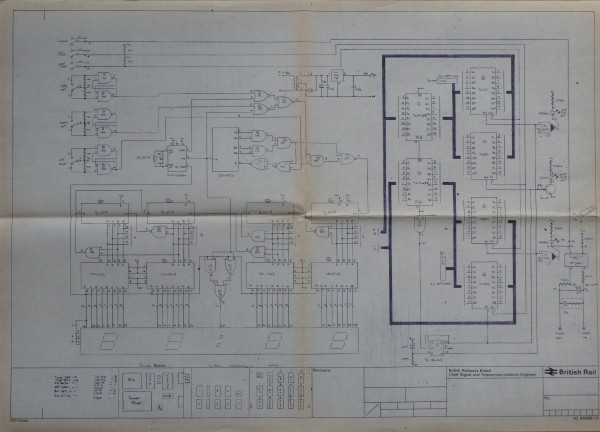
Full final circuit diagram.
![]() My concept design.
My concept design.
![]() The circuit diagrams including updates.
The circuit diagrams including updates.
![]() Front Panel layout.
Front Panel layout.
Programmable Clock Timer - 1987
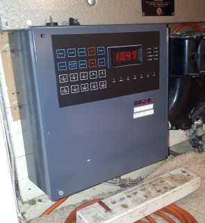 Long before the phrase 'Smart Home' became common terminology there were projects such as this that would provide simple seven day multiple on/off timing. The TMS 1601A Programmable Clock Timer IC wrapped
up in this RS Components project gave me the opportunity in 1987 to wire in a few sockets in my house that could be programmed to switch on and off at various times of the day..simple security!
The timer gave 4 independently switched outputs, 0 to -9V, which I interfaced to Triac's via opto triac drivers with zero volt crossing to switch the mains supply.
The timer gave excellent service until
I removed it in 2018 (31 years!) when Smart Home technology came of age.
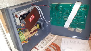
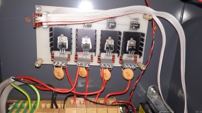
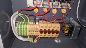
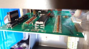
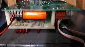
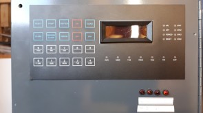
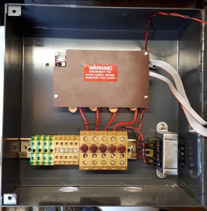
Below are the RS datasheets and my scriblings for my mains interface design - Warning - don't go near with the mains supply unless you are suitably qualified.
![]() RS Datasheet 6913 - TMS1601A Programmable Clock/Timer IC RS 308-821
RS Datasheet 6913 - TMS1601A Programmable Clock/Timer IC RS 308-821
![]() Programmable Clock/Timer PCB RS 434-699
Programmable Clock/Timer PCB RS 434-699
![]() Programmable Clock/Timer Keyboard Display Legend PCB RS 4335-182
Programmable Clock/Timer Keyboard Display Legend PCB RS 4335-182
![]() Programmable Clock/Timer Mains Interface
Programmable Clock/Timer Mains Interface
![]() Programmable Clock/Timer Mains Interface PCB layout
Programmable Clock/Timer Mains Interface PCB layout