Introduction
In the mid to late 70's, there was very little in the way of afforable mixing desks so I thought I would turn my two interests, electronics and recording to producing a good quality, low noise desk.
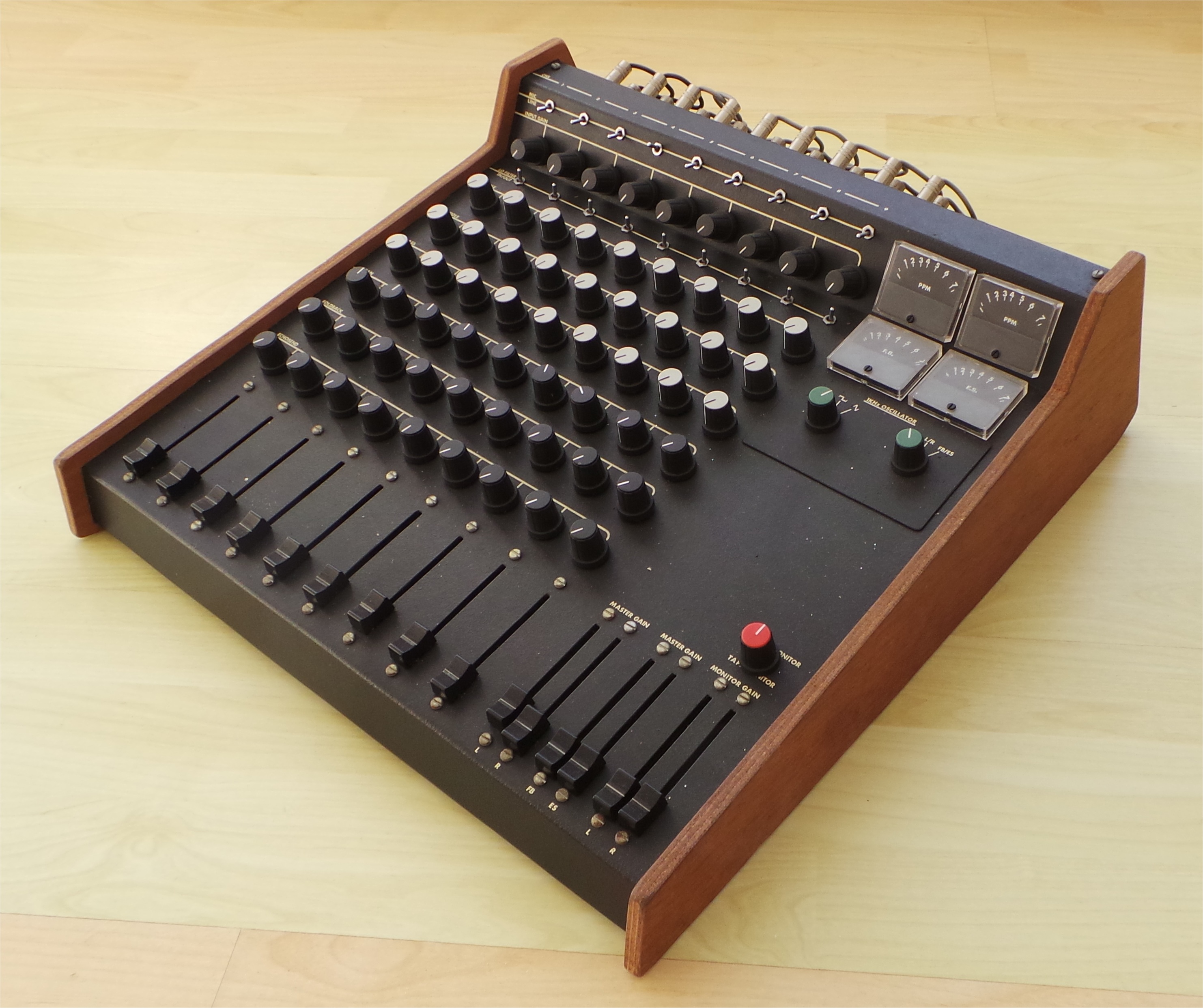
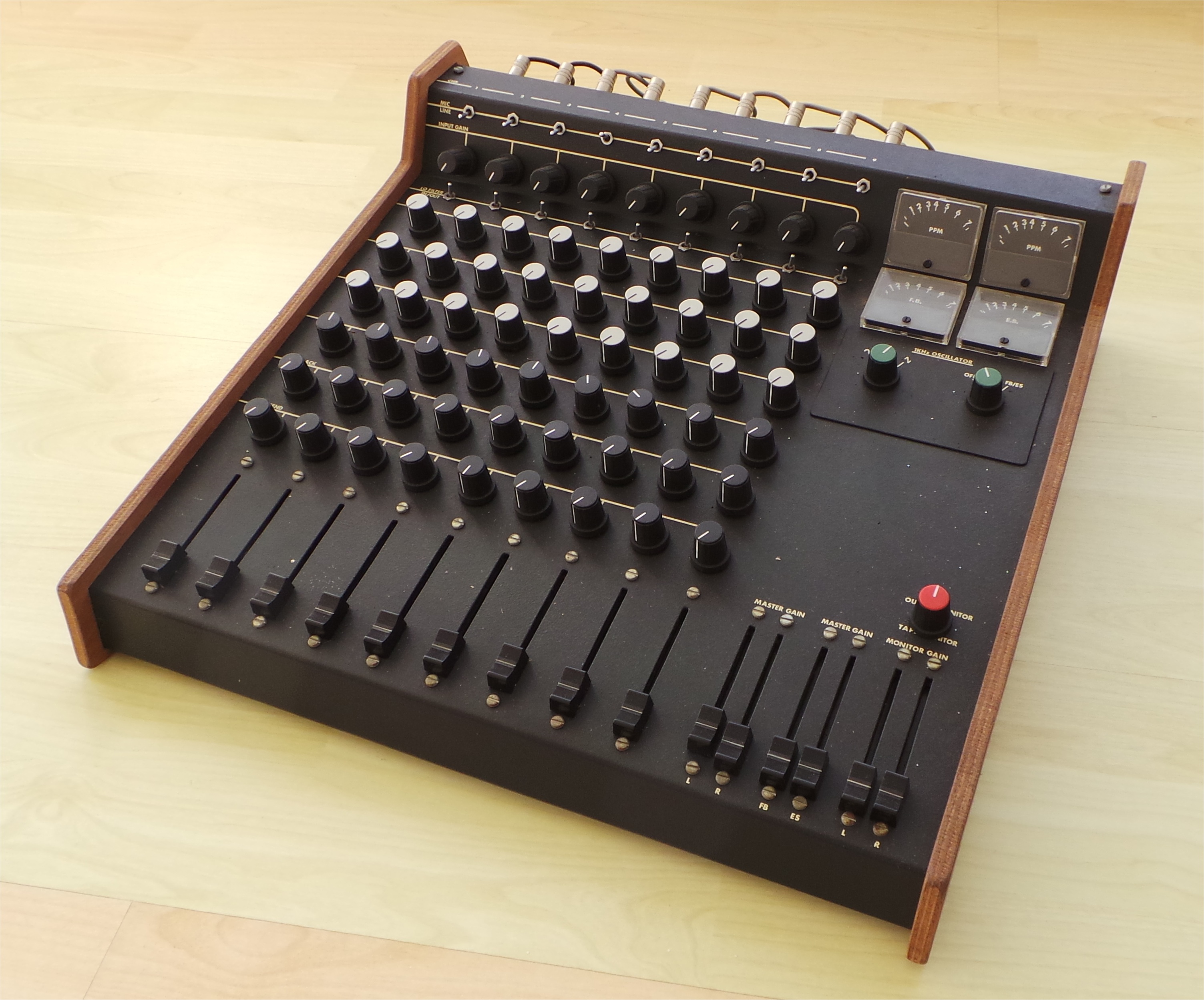
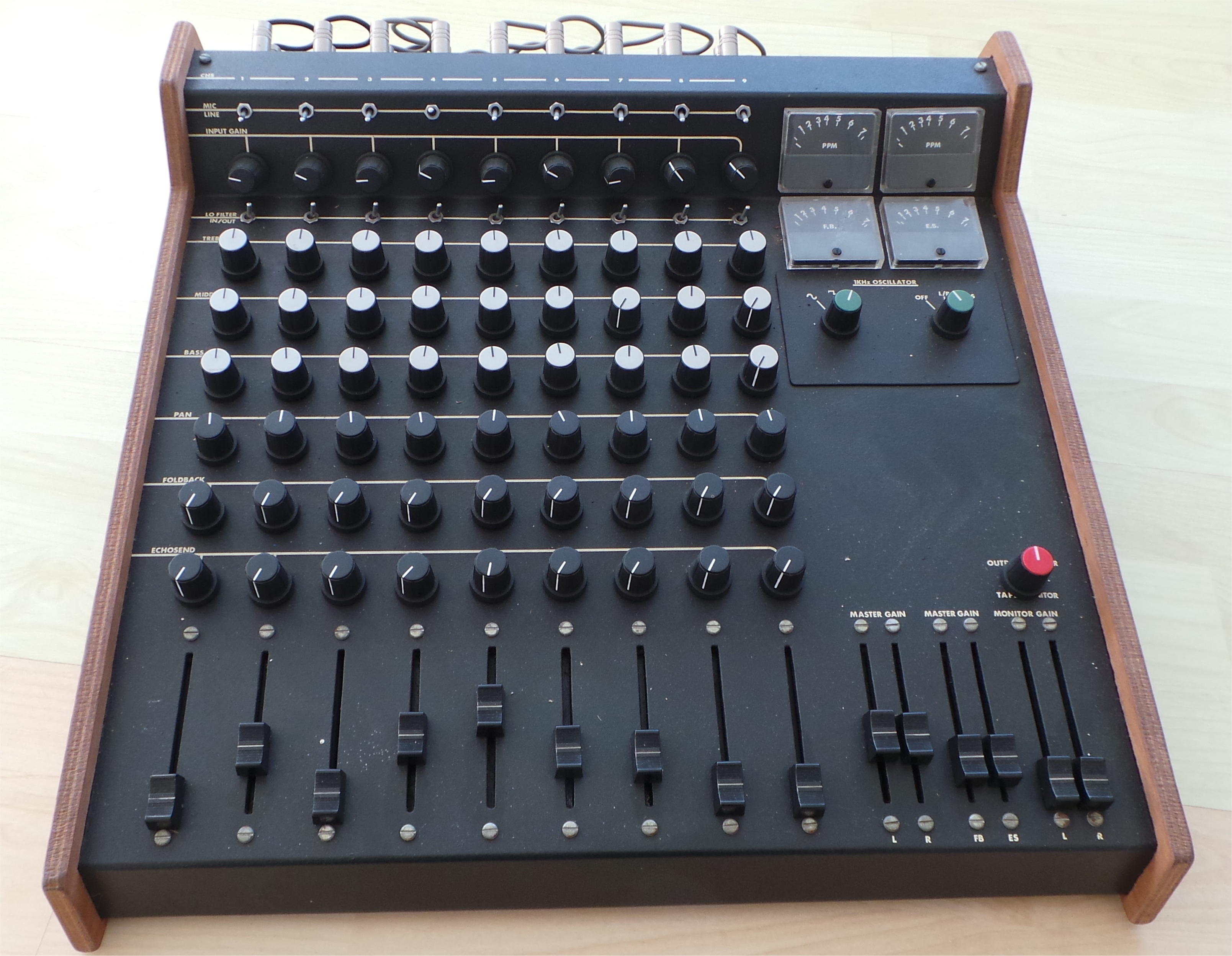
The design of each channel consists of:
Mic/Line-In - Balanced/non-balanced mic with variable 40db gain, line-in 1Vpp, both with rumble filters
Three band equaliser
Pan signal anywhere within a stereo image
Mixed Fold Back output
Mixed Echo Send output
Channel level slider
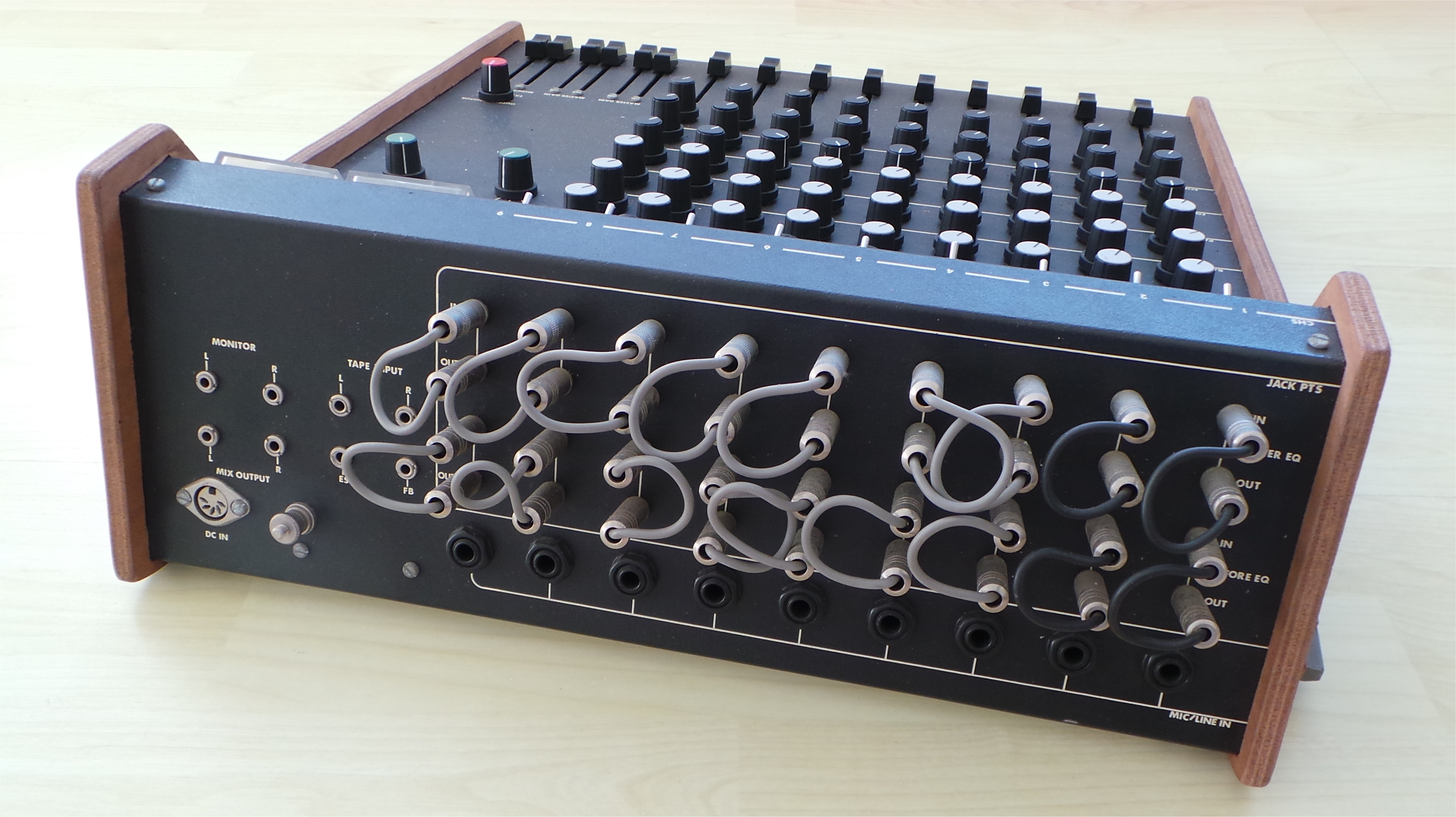
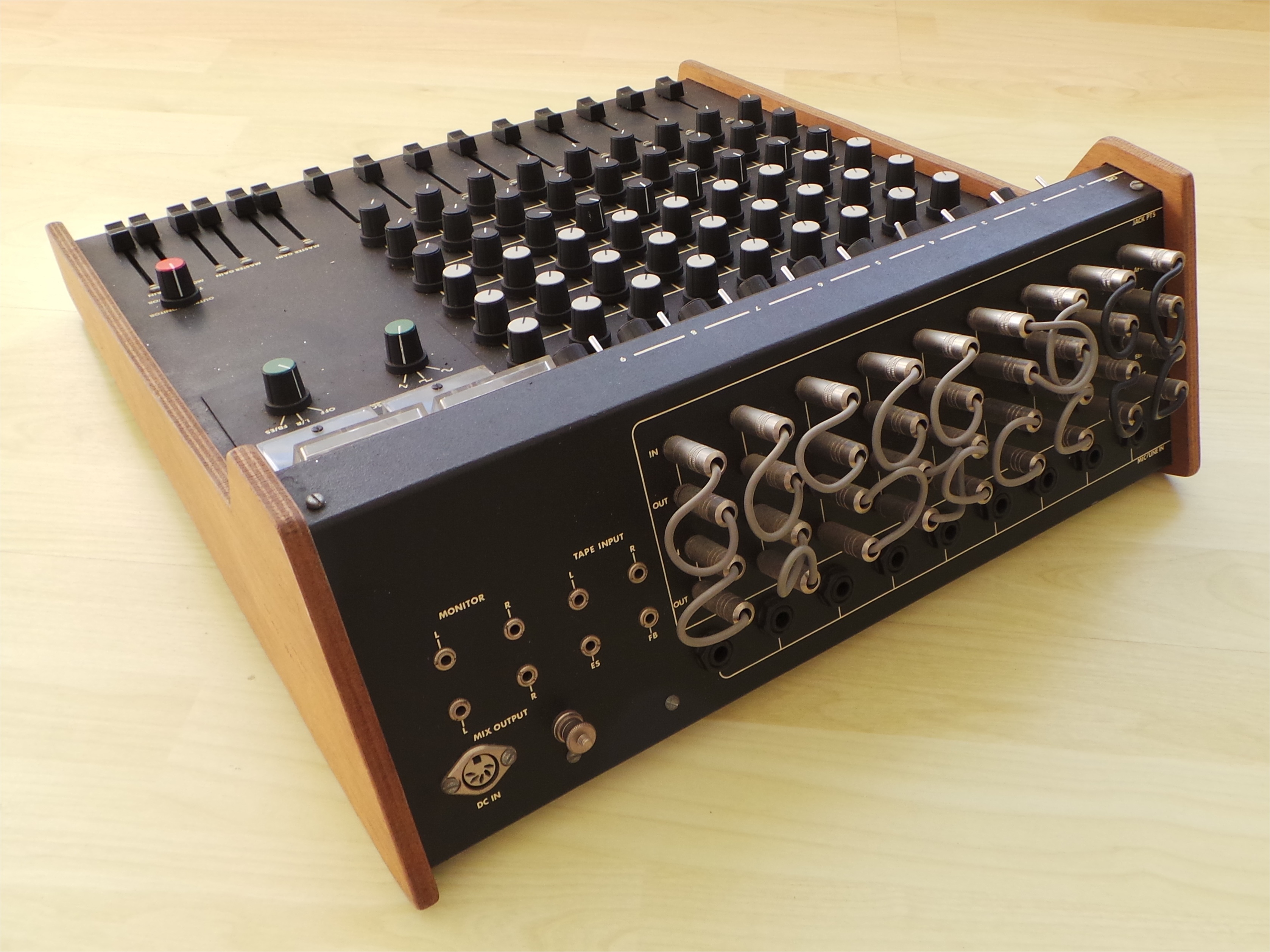
Capability to break into channel after the mic/line-in and the equaliser
Common functions:
Left and Right channel overall gain sliders
Monitor Left and Right channel overall gain sliders
1 Khz oscillator (sine/square/triangle), switchable to master or ES/FB outputs
PPM meters for each channel
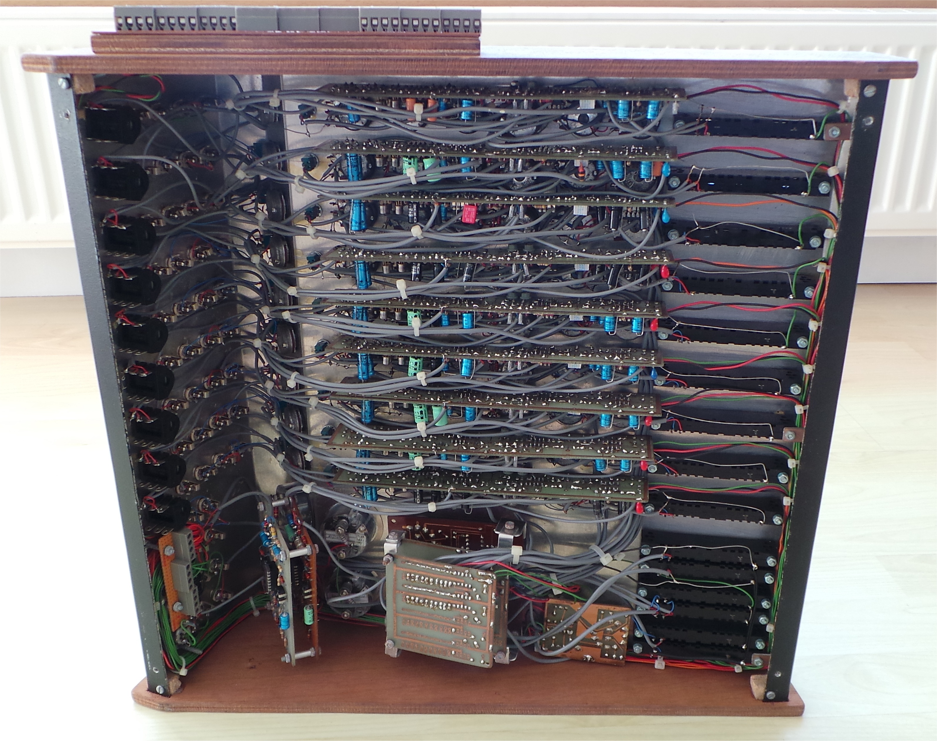
I built each channels' electronics on a single PCB with additional boards for the mixers and PPM meters. The case was custom made from aluminium and plywood with the facing painted, lettered and varnished.
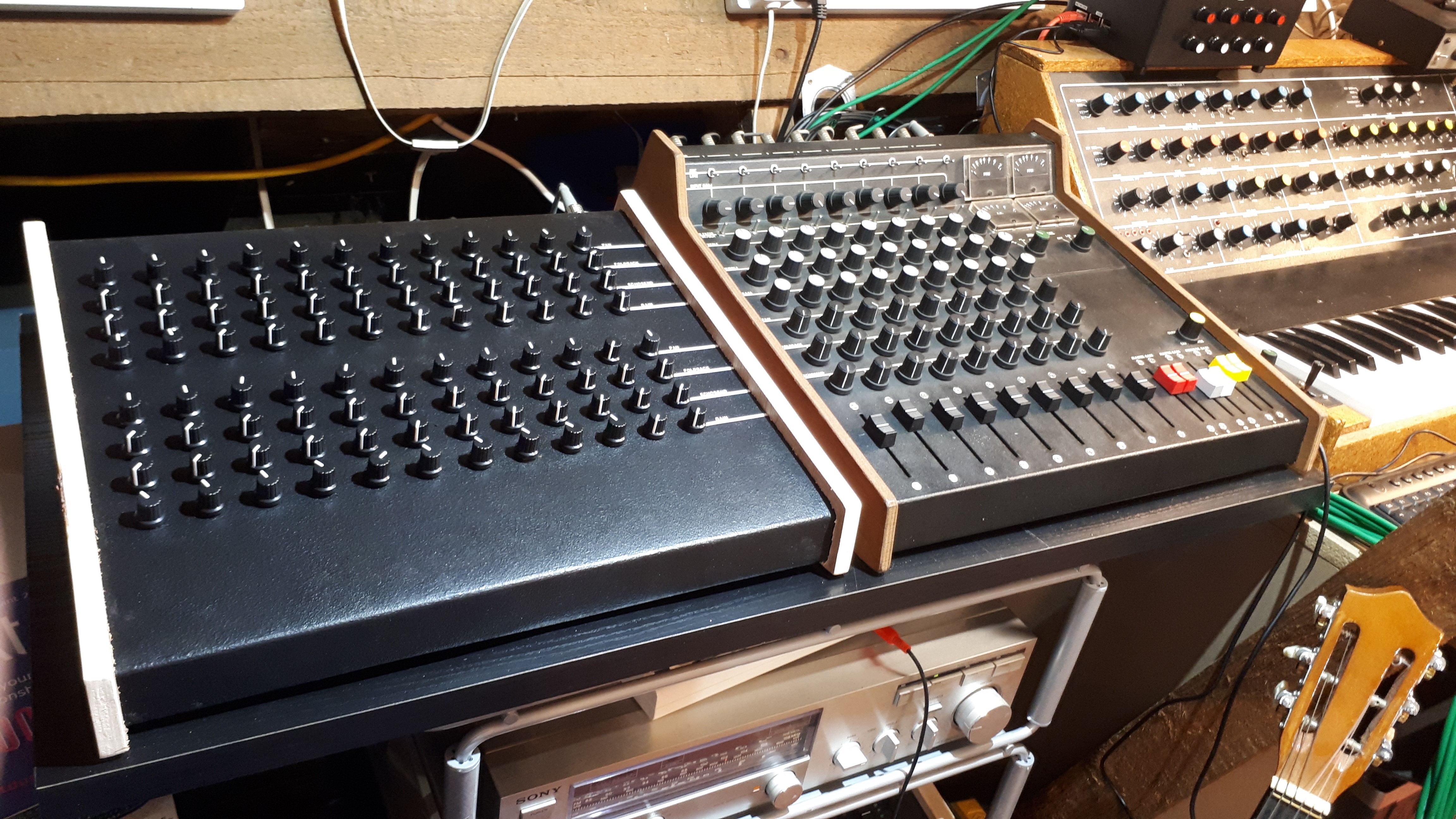
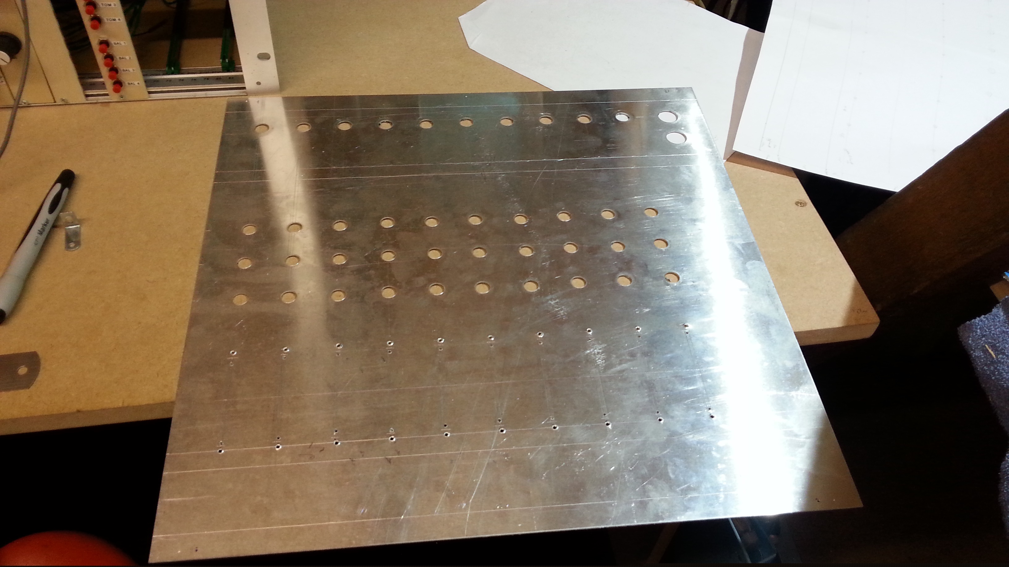
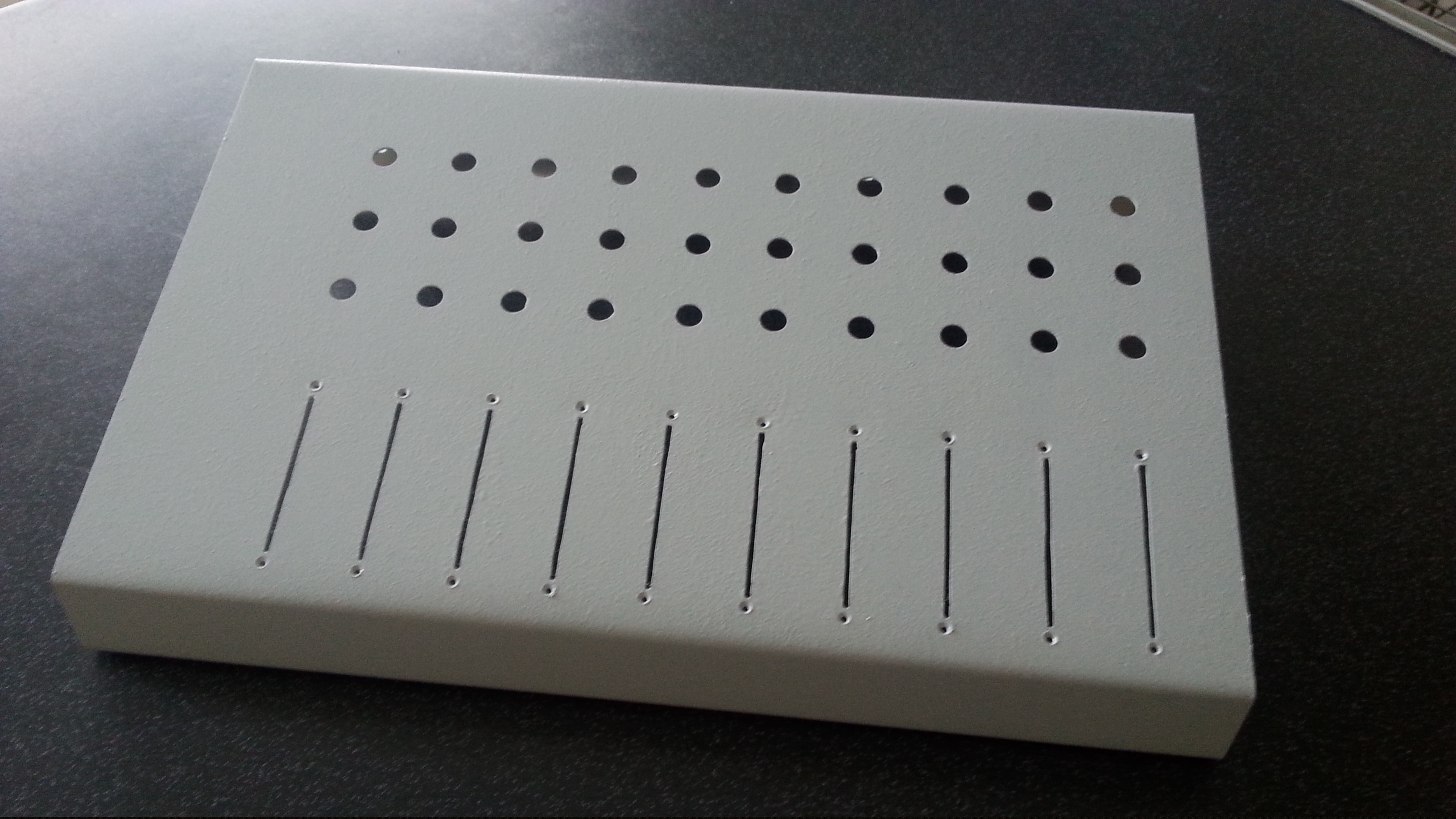
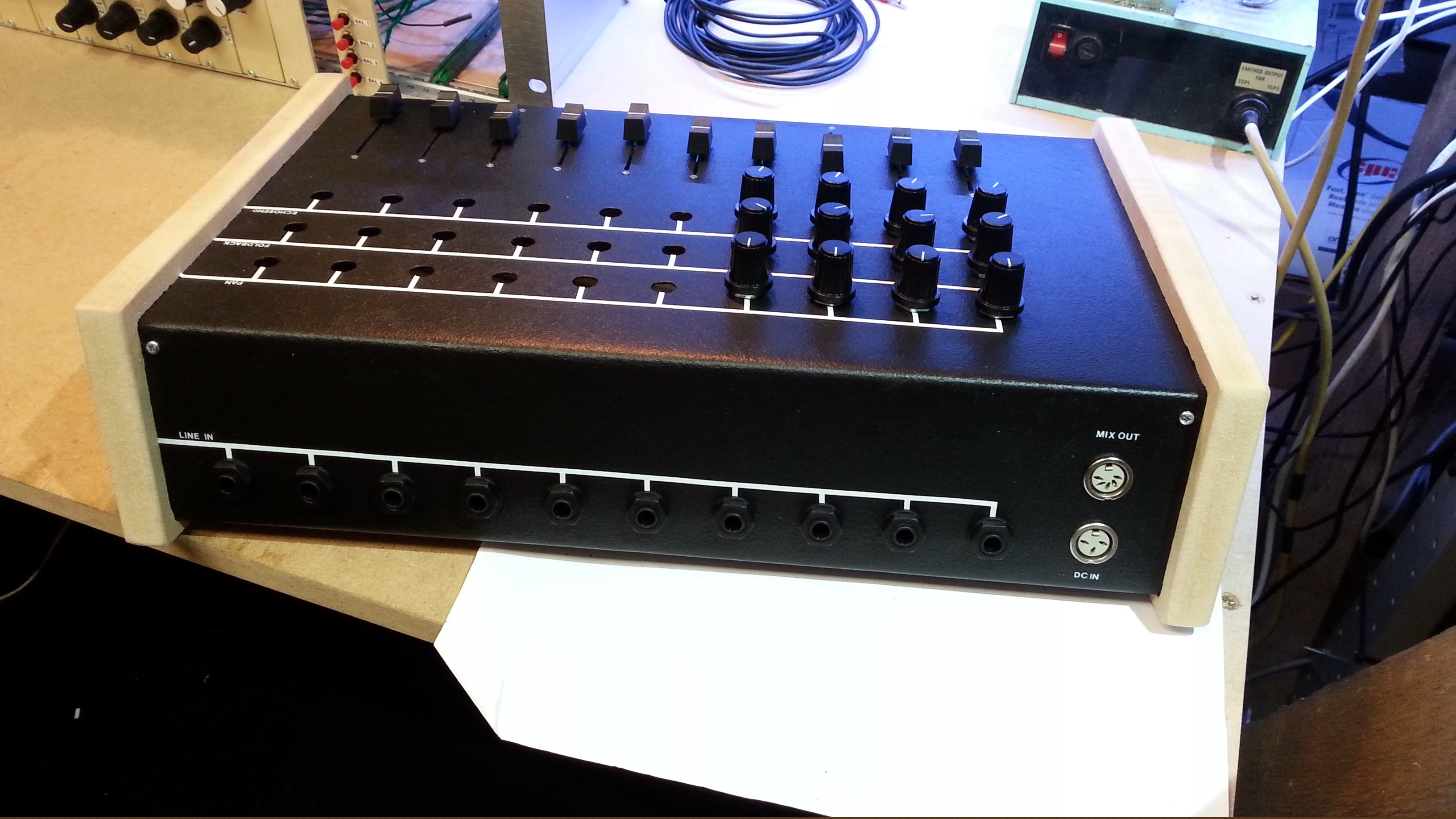
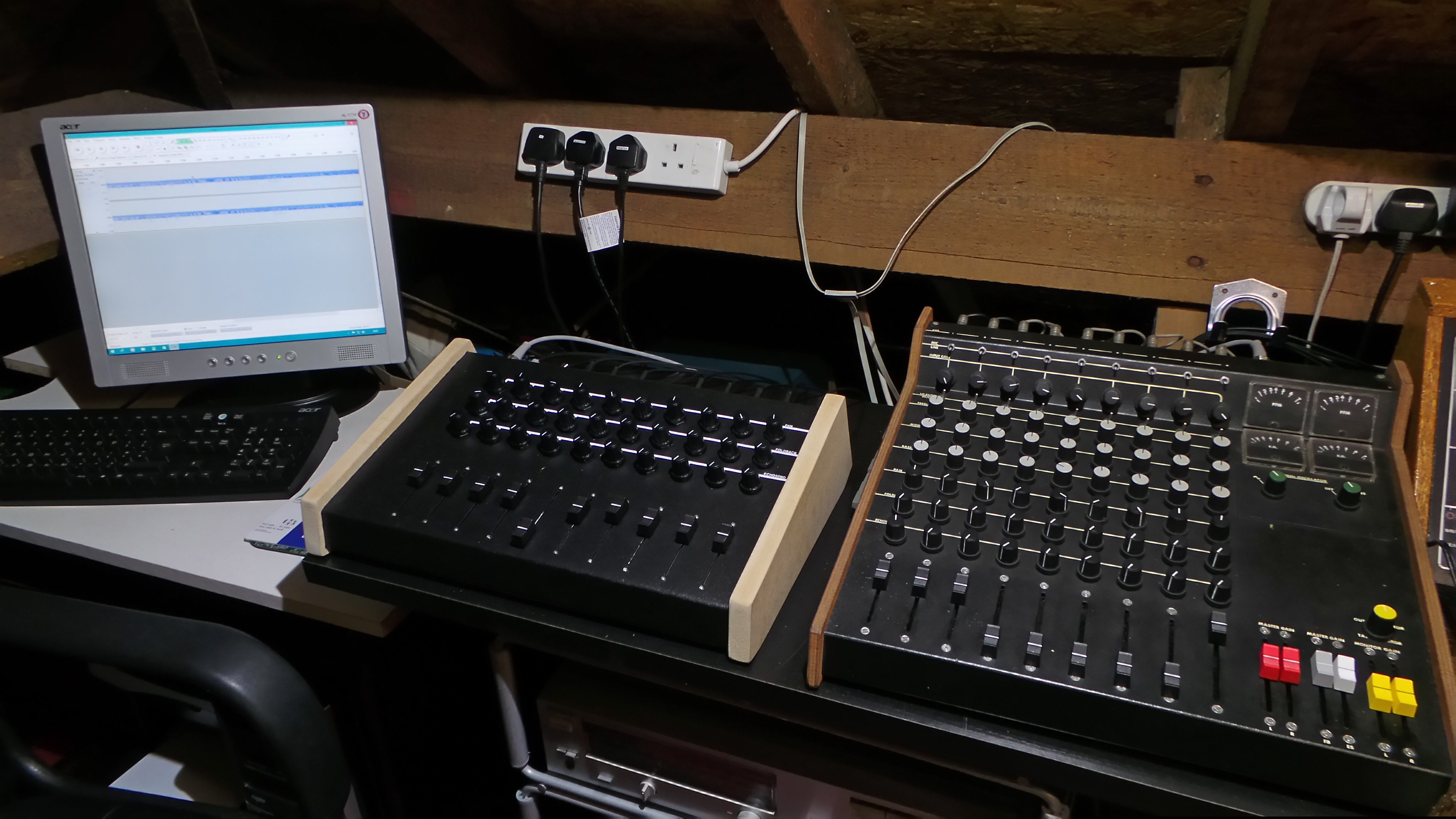
10 Channel extension - At the end of 2016 after finishing the Syntom/Symbal drum effects I needed additional mixer inputs so 35-40 years after building the mixer I built a 10 channel extension. I simplified the build by excluding the equaliser, Mic input and no break in points but later added Mute buttons and LED VU meters. There are some photos below.
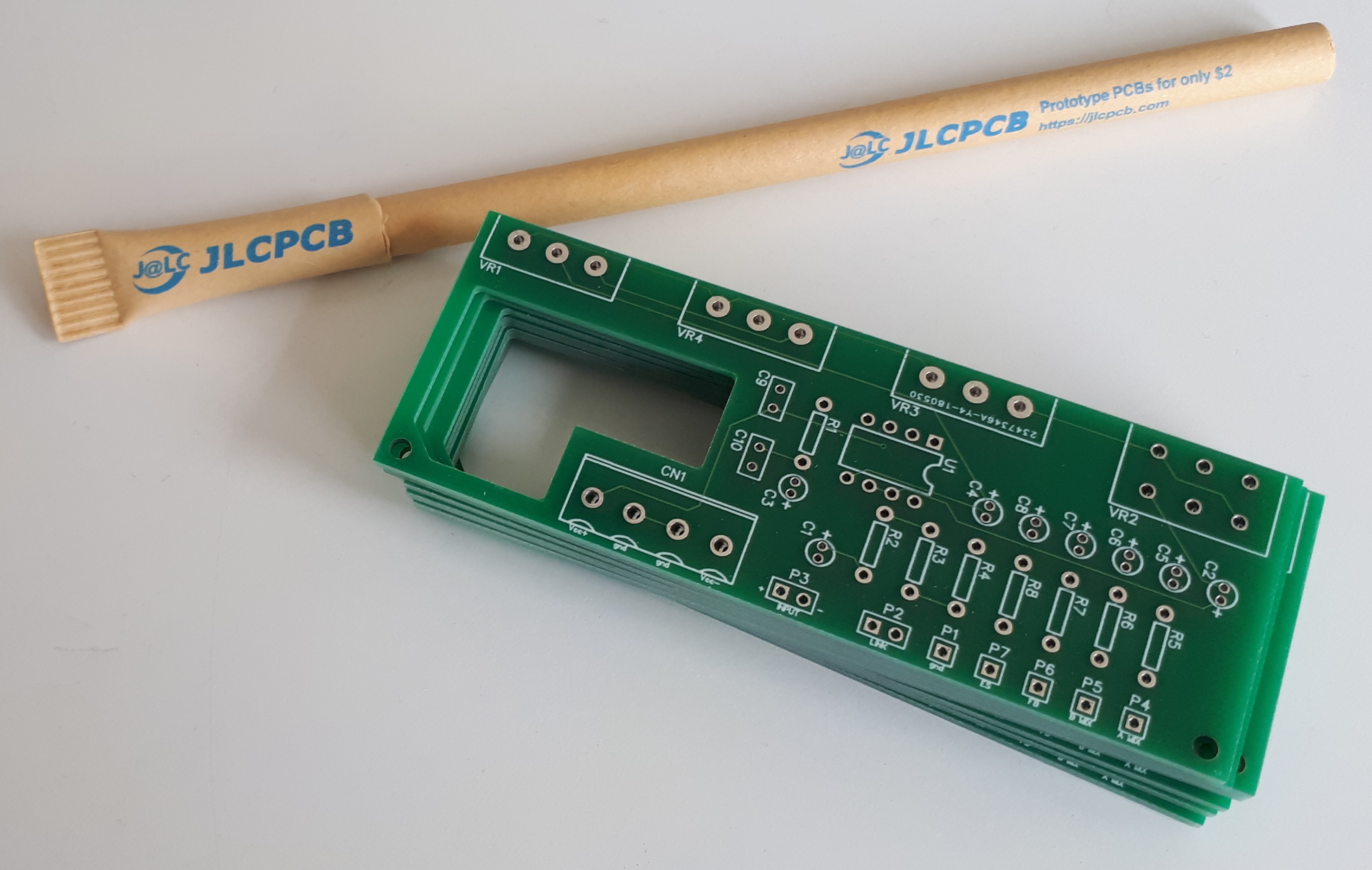
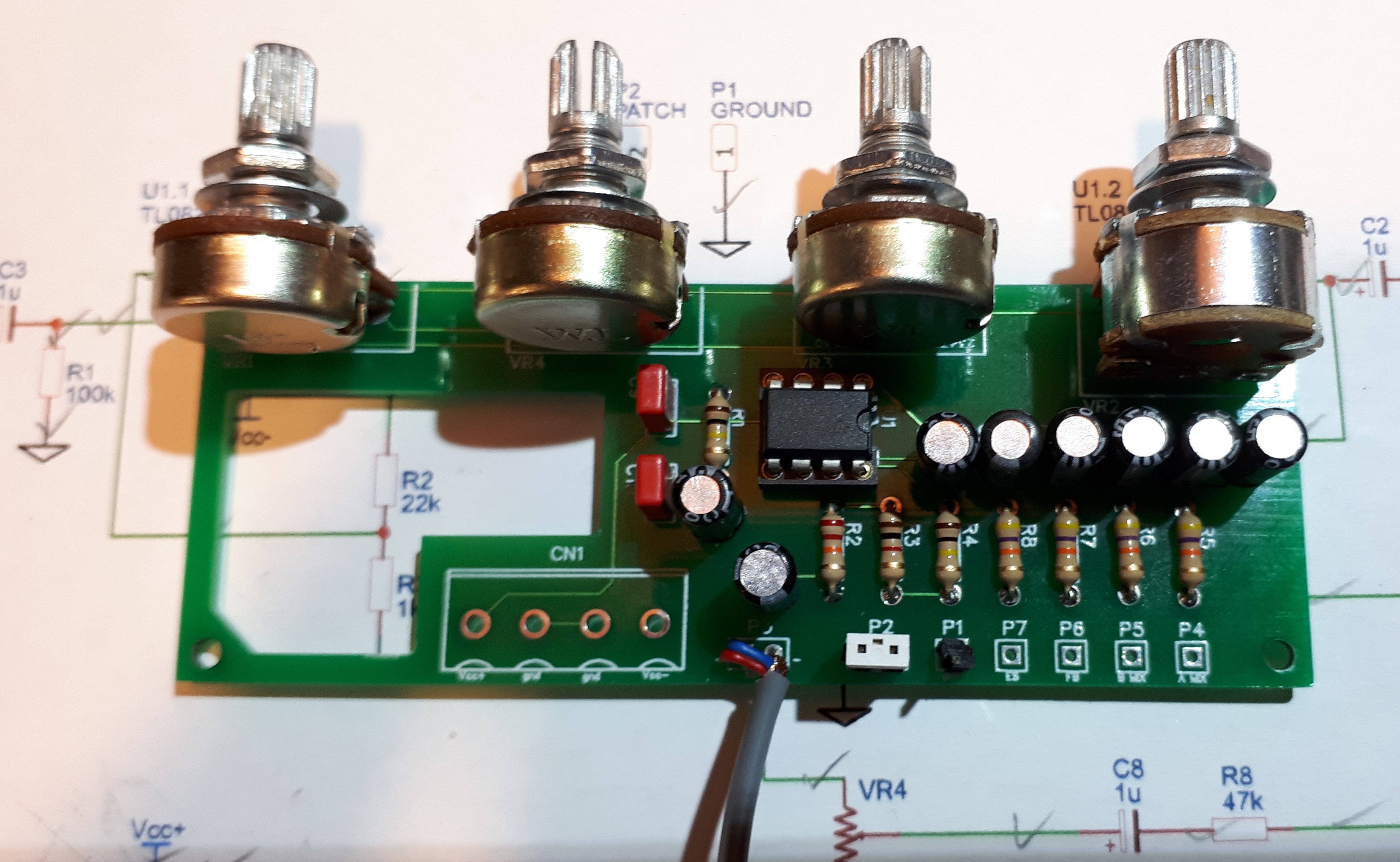
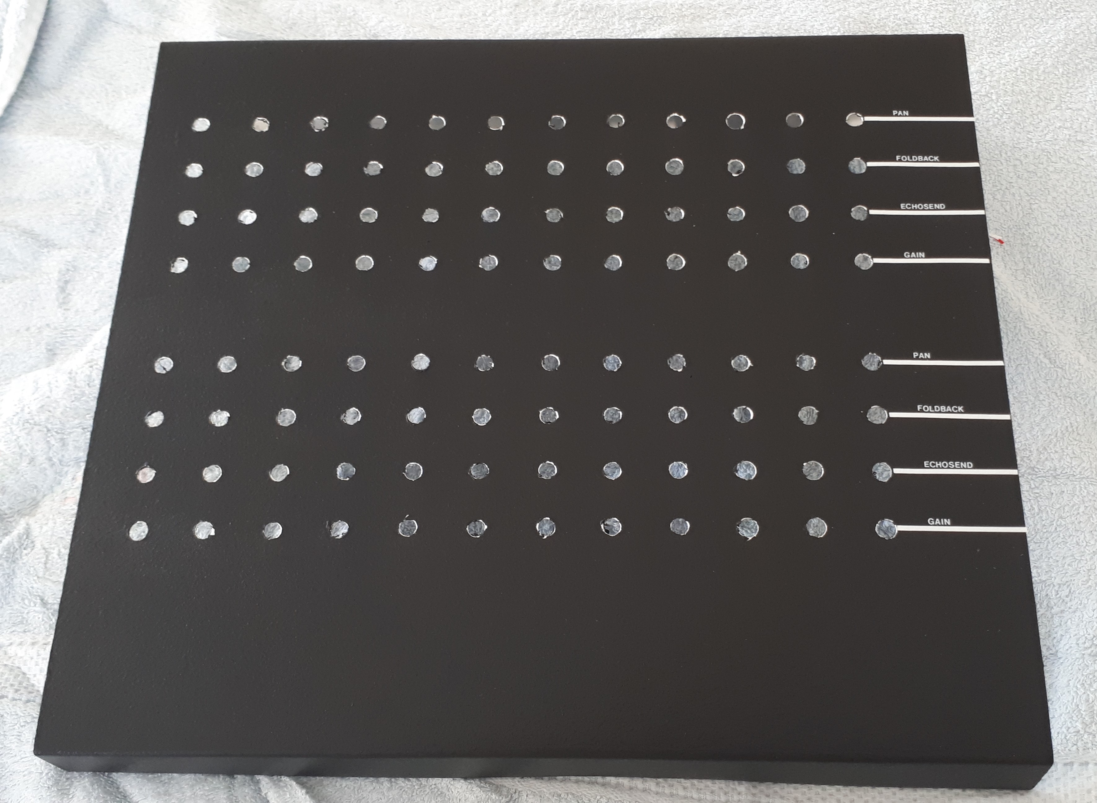
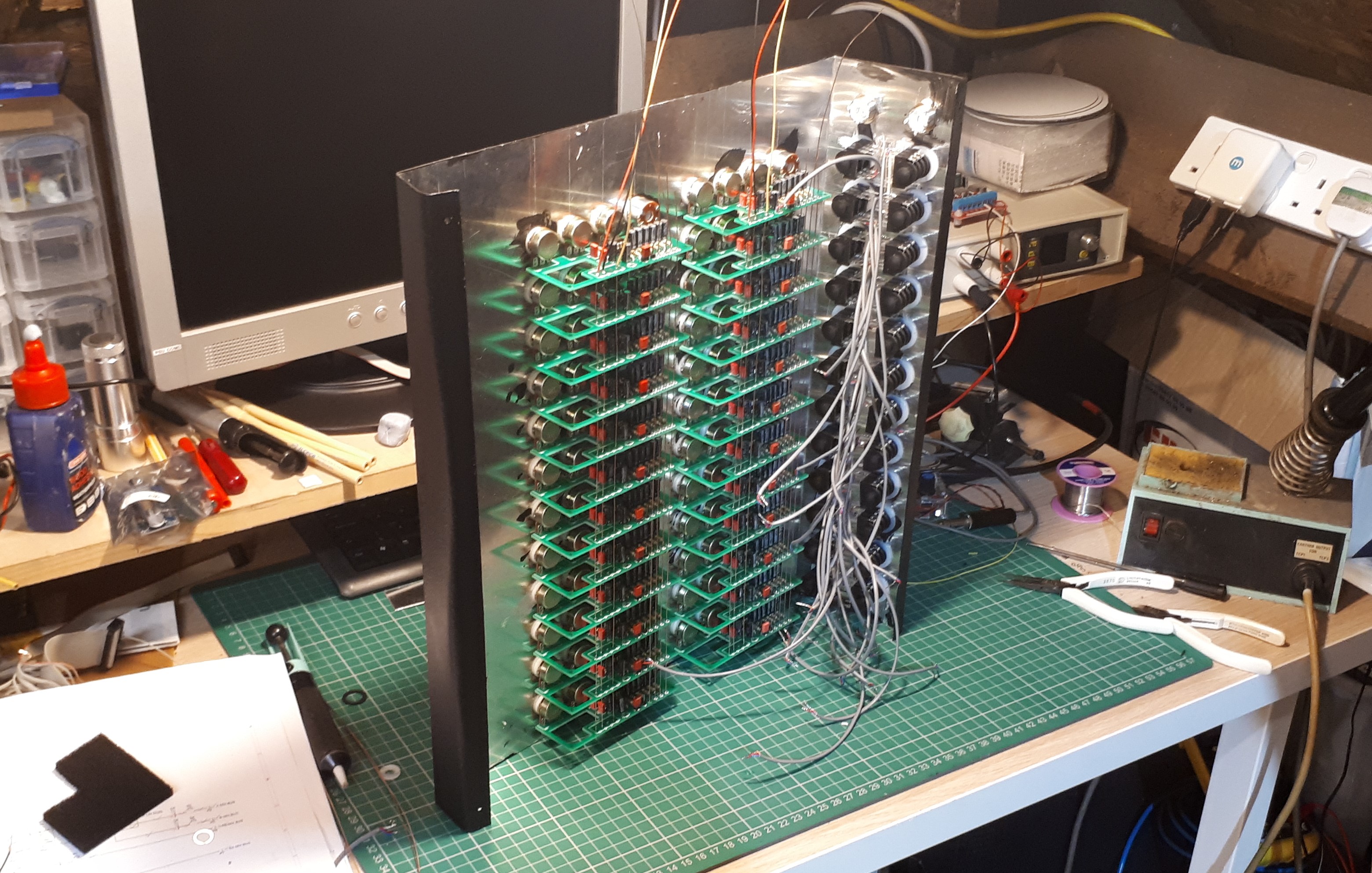
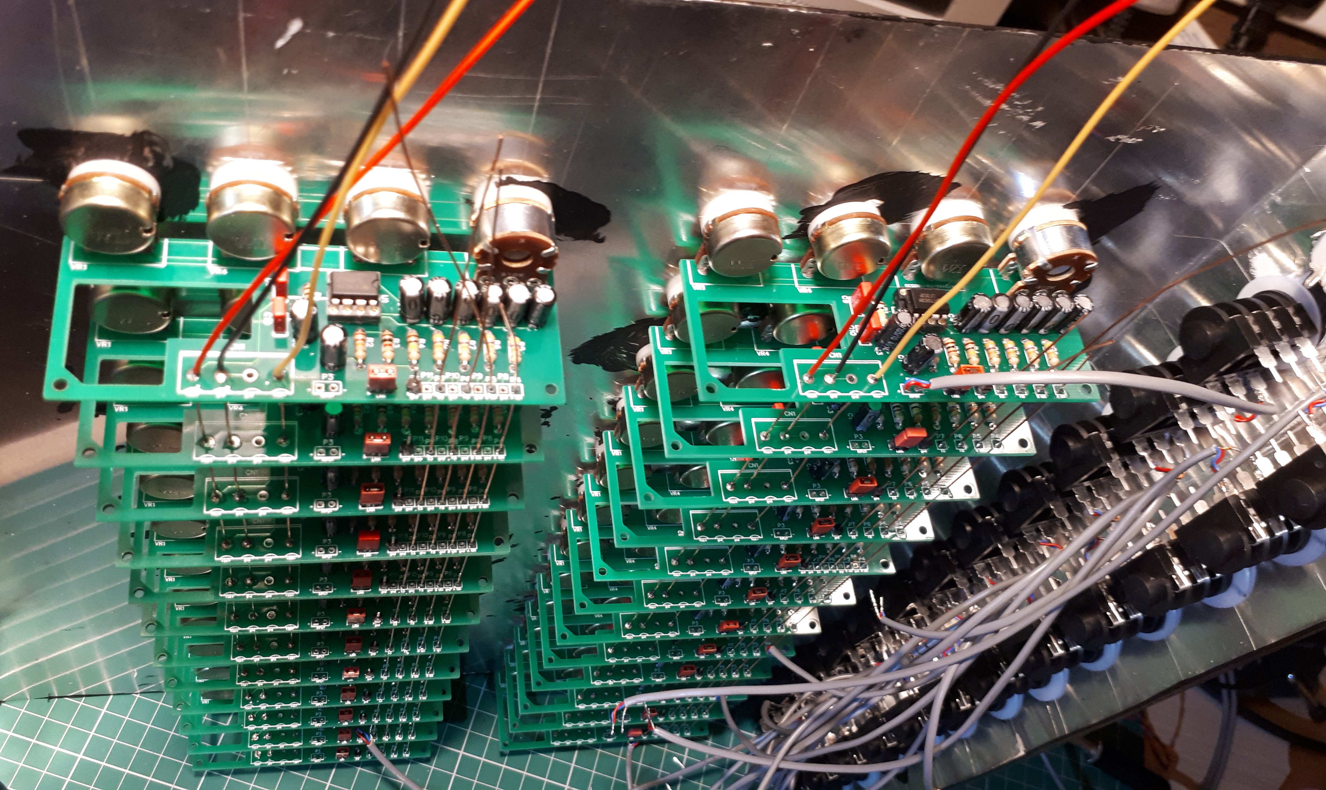
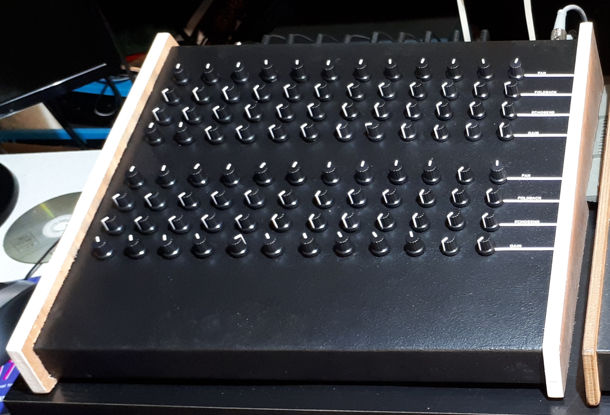
24 Channel extension - Having built a range of drum machine projects with the Raspberry Pi I found that I was running out of channels on the mixer and that the 10 channel extension was far too small. The basic channel design from the 10 channel extension has proved to be all I need so I used that as my starting point. To simplify the wiring design and metal work even more I did away with the slider controls and replaced them with rotary potentiometers - this meant that all the components could be mounted on the PCB. The electronics for 10 Channel extension was assembled on vero boards but as the cost of PCB's have dropped considerably in recent years I designed the circuit on EasyEDA and bought the boards from JLC PCB - this made assembly very easy. Circuit diagrams and photos of the 24 extension are below.
The set of diagrams:
Sheet 1, Maplins 50W Power amplifier - not part of the mixer
Sheet 2, Mixer and Power Amplifier power supply - not built into the mixer
Sheet 3, Single mixer channel
Sheet 4, A, B, ES, FB mixers with PPM meters
Original Sketched Diagram, A, B, ES, FB mixers with PPM meters
Oscillator Diagram, 1KHz Oscillator
24 Channel Extension, Mixer Channel
24 Channel Extension, Mixer Channel PCB
10 Channel Extension


24 Channel Extension