
By January 2020 I'd revived my Acorn Computer collection to the point where it's up, running and stable with all the basic add-ons I wanted. There is still a lot I'd like to add or alter but for now I can start looking through all the data and software at my leisure. Things still to do are: I would like to get a working Stop Press 64 board in the Electron which may be a tall order, also I'd like to add a couple of switches to the Master to switch between my ROM board and the internal Sideways RAM (done), upload the Gerbers for the TTL RGB Switch and BBRAM board (done), complete a case for the TTL RGB Switch (done), add a User Port to the Electron (done) and so on..but for now I have a clear work area to get started.
Electron setups:
 Electron 1 - Electron Issue 4 with Plus 1, Master RAM Board, Retro Hardware AP6, 2 off 32 banks of Battery Backed RAM, PRES AP3 & 4 Floppy Disc Interface, Dual Gotek floppy
disc emulators, ROM cartridge with User Port and UVIPROM EPROM Programmer. Software in the ROM cartidge is the Advanced BASIC Editor.
Electron 1 - Electron Issue 4 with Plus 1, Master RAM Board, Retro Hardware AP6, 2 off 32 banks of Battery Backed RAM, PRES AP3 & 4 Floppy Disc Interface, Dual Gotek floppy
disc emulators, ROM cartridge with User Port and UVIPROM EPROM Programmer. Software in the ROM cartidge is the Advanced BASIC Editor. Electron 2 - Electron Issue 6 with Plus 1 (Plus 1 modified for 16K ROM), Slogger Pegasus 400, DFS and ADFS, with Gotek Floppy Emulator, E2P512_UP (clocked at 8MHz)
with dual User Port and SmallyMouse 2. New 2021 - Plus 1 mod superceded with AP6 2v2 and populated with Advanced Basic Editor, HiView, HiBasic, E2P OS and
28C256 EEPROM.
Electron 2 - Electron Issue 6 with Plus 1 (Plus 1 modified for 16K ROM), Slogger Pegasus 400, DFS and ADFS, with Gotek Floppy Emulator, E2P512_UP (clocked at 8MHz)
with dual User Port and SmallyMouse 2. New 2021 - Plus 1 mod superceded with AP6 2v2 and populated with Advanced Basic Editor, HiView, HiBasic, E2P OS and
28C256 EEPROM. Electron 3 - Electron Issue 6 with Plus 1, Master RAM Board, Slogger Pegasus 400 with Gotek Floppy Emulator and ROM cartridge with User Port.
Retrobargains AMX Mouse adapter for PS/2 mouse. Software in the ROM cartridge is Stop Press.
Electron 3 - Electron Issue 6 with Plus 1, Master RAM Board, Slogger Pegasus 400 with Gotek Floppy Emulator and ROM cartridge with User Port.
Retrobargains AMX Mouse adapter for PS/2 mouse. Software in the ROM cartridge is Stop Press. Electron 4 - *New 2020* Electron Issue 2 with Plus 1, Pegasus 400 Disc Interface and Gotek floppy emulator. E2P512_UP (clocked at 4MHz) with dual User Port. This Electron is used for the Sequencer Project and
is in its final configuration.
Electron 4 - *New 2020* Electron Issue 2 with Plus 1, Pegasus 400 Disc Interface and Gotek floppy emulator. E2P512_UP (clocked at 4MHz) with dual User Port. This Electron is used for the Sequencer Project and
is in its final configuration.BBC B+:
 BBC B+ with 64K RAM upgrade (BBC B+ 128), ATPL Sidewise + ROM board, ZIF socket, RPi Co-Processor, dual Gotek Floppy disc emulators.
 BBC Master:
 BBC Master with 32-16 ROM board, dual Gotek Floppy disc emulators and Retroclinic internal Raspberry Pi Co-Processor adapter and SmallyMouse 2.
Other bits and Pieces:
2 x 6 input/1 output TTL RGB Switch, 15" LCD colour monitor with TTL input, 19" TV using RGBtoHDMI module, Retro Hardware ATI with RPi 2nd Processor, various E2P's with Dual User Ports and miscellaneous cartridges.
What follows is my journey from the inspiration to unpack my kit to having stable and upgraded systems.
Introduction
 When searching for something Raspberry Pi related but nothing connected to Acorn computers I stumbled across a reference to a Raspberry Pi second processor. Bouncing around a few links brought me to
Sundby.com which sold the PiTubeDirect signal converter and links for the Raspberry Pi 2nd processor emulator software. All this gained my interest so I opened my retro museum and unpacked loads of my
Acorn stuff - This lot of computers to the right.
When searching for something Raspberry Pi related but nothing connected to Acorn computers I stumbled across a reference to a Raspberry Pi second processor. Bouncing around a few links brought me to
Sundby.com which sold the PiTubeDirect signal converter and links for the Raspberry Pi 2nd processor emulator software. All this gained my interest so I opened my retro museum and unpacked loads of my
Acorn stuff - This lot of computers to the right.
 It turns out that my interest in the Raspberry Pi had led me rather belatedly to the Raspberry Pi Second Processor emulator project for Acorn BBC/Electron computers, my other obsession! So I thought
that I'd buy the interface and give it a go. I ordered the Sundby PiTubeDirect interface external kit which I'll use with a Pi Zero. Learning of this project rather late in the day made it
fairly easy to put together as it's well documented, anyway I'm getting ahead of myself, I had to find out if my collection of Electrons, BBC B+ and Master were still working after being in
storage for such a long time. First was the BBC Master..
It turns out that my interest in the Raspberry Pi had led me rather belatedly to the Raspberry Pi Second Processor emulator project for Acorn BBC/Electron computers, my other obsession! So I thought
that I'd buy the interface and give it a go. I ordered the Sundby PiTubeDirect interface external kit which I'll use with a Pi Zero. Learning of this project rather late in the day made it
fairly easy to put together as it's well documented, anyway I'm getting ahead of myself, I had to find out if my collection of Electrons, BBC B+ and Master were still working after being in
storage for such a long time. First was the BBC Master..
As this page is quite long I've added some quick links to make it easier to jump into any particular topic:
BBC Master | BBC B+ | Electron | Disc Drives | RGB Switch | Battery Backed RAM
| UVIPROM EPROM |
Electron User Port | Electron Second Processor | Monitors | ROM Cartridge with User Port | Plus 2 |
| Testing 6502's
BBC Master 128 32-16 ROM Board EasyEDA Project Page
A week later I switched on the BBC Master for the first time in many years, needless to say the batteries were exhaused and therefore the configuration lost. The batteries were dated 2001! amazingly
after 18 years they hadn't leaked. As it's been a while since I've used an Acorn machine I had to re-aquaint myself with the *configure command and now it's all working perfectly.
Since the
Master was OK I re-manufactured my 32-16 ROM board from the '90s so I could install my inter series ROMS inside. More info on the BBC Master page.


![]() The Master 32-16 ROM Board
Gerbers and Schematic.
The Master 32-16 ROM Board
Gerbers and Schematic.
There are times when it would be useful to have access to the Sideways RAM so I considered fitting a couple of toggle switches on back of the Master wired to links 18 and 19 to select between ROM
and RAM. The rear of the Master has a steel plate which I thought would take a little effort to drill through so I decided to fit push switches internally on the links - after all I never have the
lid screwed on so it's easy to lift the lid to flick a switch!


Internal RPi Co-processor
August 2020, While randomly looking on Ebay I came across the Retroclinic internal Tube level shifter so I thought I might as well build the RPi co-processor into the Master. My small level shifter
is 1mm too big to fit under and into the Tube socket so instead of going to the trouble of modifying it I just bought the internal board.


The board arrived fully assembled, I just needed to plug in the Pi then plug both into the internal sockets..very easy. I had been through the learning curve of creating the SD card before so it was a simple
matter of formatting a card in FAT32 and copying the files on to it.
It worked first time which was a surprise as the Tube was configured to ExTUBE, I changed to InTUBE but I think some further reading about the configuration is required!
BBC B+ 128
Another few days had passed before I got the chance to switch on the BBC B+. All was well for the first ten minutes then I could hear a faint buzzing sound, not long after the dreaded smoke genie appeared!
I think I was quick enough to switch it off before there was a lot of damage. The smoke came from the power supply area so I disconnected the mains supply and removed the PSU and striped
it down - the fault was fairly obvious, the suppression capacitor C2 had smoke damage as you can see in the photos. I've ordered a replacement and we'll see what happens next..
After a quick look round the internet it seems that it's a good idea to replace the smaller 10nF capacitor C1 as it's the same type. Looking at the capacitor it is showing signs
of age/stress/swelling and I don't want to dismantle the supply again so it'll be replaced..
A few weeks later I received the parts and replaced both suppression capacitors, a tricky task as once the capacitors have swollen it's difficult to get them out due to the
tightly packed neighbouring components - you can see the problem in the photos. I put the power supply back in the BBC case and before connecting up tested each of the power lines - all was ok.
So that's the BBC B+ back up and running - good for another 40 years!
On getting the Raspberry Pi 2nd processor up and running on the Electron I thought I'd build one for the BBC B+. I've got no space to put my Acorn 2nd Processors on my desk and with the Pi
2nd processor being able to fit under the BBC it would be prefect for me. I have had some experience soldering surface mount components but I'm never very happy with the results so needless to say
I am not keen on using surface mount devices. I thought I'd simplify the interface by making a Level Shifter PCB using standard DIL devices. Even when using the larger devices it still fits
neatly under the BBC.
I said it would last another 40 years..it hardly lasted another 40 days until it wouldn't power up properly! Removing C9 it could be seen that it had swollen on the underside so I replaced it then
rebuilt & tested the supply. All is well again but for how long...


With the trackerball reterminated and working again (see below) I started to resurrect Technomatics Novacad (see above!). I had forgotten how much I liked this CAD package.
Electron
Unpacking my box of Acorn computers revealed two Electrons, three Plus 1's and a Pres Plus 3/4, when tested the Electrons and the Plus 1's worked ok except for the disc drive PSU and
three keys on one of the Electron keyboards.. The Electrons are issue 6 and 4 and the three Acorn Plus 1's are all issue 2's.
Edit: end of 2019, when looking through some boxes for my Marconi trackerball I found a third Electron / fourth Plus 1 and more data disc's. They were hidden amongst my Amiga 1200/600's.
Still no sign of the trackerball though.. Opening the Electron shows that it's an issue 6 and has had a few modifications added, two are around the composite video output, one on the cassette
interface and a piece of foam/cardboard placed in front of the speaker to reduce the volume. They won't affect my use of the machine so I'll leave them as is. Switching on revealed nothing unexpected,
the Plus 1 does have a copy of the PRES Plus 2 ROM though. I think this Electron would have been given to me when I was involved with the EUG..there was a lot of trading of computers and parts back
then so much so that an EUG member, whilst on holiday in Scotland, randomly turned up at my door and bought a disc drive! There are some photos of this Electron below the MRB photos along with some
ROM cartridges.
I replaced the PSU and used switch cleaner on the keys so everything is now up and running. My aim for the PiTubeDirect & Raspberry Pi Zero is to get a stable 2nd processor working on the Electron.
Years ago I bought a Jafa 2nd Processor which worked fairly well but over time became too unstable to use. I only used the 2nd processor for large documents written in View and occasionally with
Starword, I eventually replaced it with the Slogger Master RAM Board. I no longer have either of these add-ons so the 2nd processor emulator is an interesting replacement.
To run the 2nd processor emulator on an Electron it requires a TUBE interface. Research brought me to the Retro Hardware ATI which not only has the TUBE interface but two 16K sideways RAM banks
which will come in handy for running View. I assembled the PiTubeDirect interface which was a bit fiddly due to the surface mount components. Care has to be taken mounting the 40 pin headers as it's
easy to solder them in the wrong way round. Also when creating the SD card the instructions state that the card should be formated 'standard FAT' which I took to be FAT16. This can be done but it's
a bit tricky with cards greater than 4Gb so I also tried FAT32 which works just fine. With everything assembled it all worked first time, I have run the test programs but yet to try View etc.
Just had five minutes to try an old EUG disc I found, issue 18, the opening screen of the EUG being munched by a dot - what an amazing speed increase with the second processor! I wasn't expecting much
of a speed increase with View and I wasn't dissapointed, the only upside is that 30462 characters are available in any screen mode. So far nice and stable..
To help bring my Electron back to what I used in the early 90's I've fitted an AP6 ROM expansion board to my Plus 1 and a Master RAM Board (MRB) to my Electron issue 4. For a pictorial walk through showing
the fitting of a MRB to an Issue 6 Electron click here.


Electron Issue 2

A couple of things prompted me into buying this issue 2 Electron on Ebay, I had dedicated an Electron to my Synth setup so I was one down and I wanted to keep three Electron systems built with
different levels of peripherals.
When it arrived it just needed the case cleaned inside and out and about five keys sprayed with switch cleaner then it was good to go.
The basic configuration for this one will be the Electron itself, a Plus 1, a Disc Interface with Gotek and some internal ROMs, probably with an AP6. I had a spare Plus 1 and so far I have
added the Pegasus Interface and Gotek drive.
A short time later I found that the Analogue port on the Plus 1 was not reading the input voltage value correctly so I traced the fault to a couple of ground pins on the its 15 Pin D Sub socket.
I tried cleaning the contacts but to no avail so a new D Sub socket will be fitted. During that search I also found that the voltage on the Plus 1 was only 4.74V, this was traced to a dirty
edge connector on the Electron. Once cleaned the voltage was back up to 5.01V


Electron Disc Interfaces
'Back in the day' when there were three choices of WD1770 disc interfaces, Acorns Plus 3, the PRES AP3/4 (pictured above) and Sloggers Pegasus 400 I chose the buy the PRES AP3/4 and a collegue
bought the Slogger Pegasus 400. I'd always thought I'd made the correct choice as it looked more professionally finished and generally used the same commands as the other DFS/ADFS in the
Acorn range. Recently when I wanted to upgrade an Electron the only Interface available at a sensible price was the Slogger Pegasus 400, on Stardot there was some recovered bare boards that
were brought back to life and made available to enthusiasts. I bought one and have been very pleased with its operation.
And even more recently I wanted to extend another Electron and bought what may have been the last Pegasus board (also pictured above) which at the time was sold to me with the caveat that
it may be faulty. I duly did all my homework finding the diagram, photos of the PCB and read up on as many common faults as possible. I was told that some of the PCB's could have faulty
tracks or via's and I found out that the RAM chip had to be an 8K device - a small mod was required to use the now more common 32K device.
When the board arrived I 'belled' out every track on the board, no faults found there! during the testing I found that the RAM device was a 32K and that the Mod still had to me made. I put the
whole lot back together and before making the mod I tested the interface. I found that the drive was constanty re-trying and occasionally succeeding to get data from the disc but would eventually fail.
Post mod the interface and drive worked perfectly.
As this may have been the last of the original Slogger boards I thought I should try and preserve this design for future users by reproducing the PCB. I also wanted to include the RAM modification
and to fix the mounting hole issue where a hole is almost under and IC. So here it is:


New blue edition..


Disc Drives
Each machine has it's own disc drive(s), the Master has twin 5 1/4" drives, the BBC B+ a single 5 1/4" drive and the Electron a 3 1/2" drive. There is a disconnect with this arrangement which is that
the Electron is isolated, I cannot transfer programs/data between the Electron and the other two computers. I decided to solve this problem by adding a 3 1/2" drive to the BBC B+ giving it both sizes
of drives.
I found an old 3 1/2" drive and ribbon cable from by PC spares (junk), a USB power supply and made up a USB to Floppy 5V power cable. The cable was made up from old PC drive 'Y' cable - two molex and
one floppy connector, a resolderable USB connector and some 2-core 3A mains cable. I cut the floppy connector off leaving plenty of wire, soldered and sleeved it onto the 3A cable then soldered the
USB connector to the other end. The use of the fairly heavy cable is to ensure minimal volt drop accross the cable when the drive is taking peak current ie when the stepping motor is stepping. Connecting
the drive to the Electron PRES Plus 3 with the ribbon cable and plugging in the usb power adaptor for testing, no problems were encountered and as the drive defaults to drive 1 this makes it easy to connect to the existing
BBC B+ drive which has its drive set to 0 - no link swapping or cable core twisting was required. All I need now is a 34 way IDC connector to press onto the existing 5 1/4" drive ribbon cable.


And to add to the mix is this GOTEK Floppy drive emulator - I intend to plug it into the BBC B+ along with the 5 1/4" drive so I can copy years worth of documents that have been stored away since the 80's.
Then it'll move around the computers as required.


Having spent a day using the GOTEK I will consider replacing the old disc drives with these units. I've been copying data onto the GOTEK from floppy discs that have been stored in drawers for around
35 years..1984 or even earier! One paricular make, Parrot, hasn't stood the test of time but they have all suffered in such a way that the disc struggles to spin, probably due to the disc surface swelling.
I think I've worn out the heads on at least one drive! The photo above is the pile of about fifty discs that are no longer readable, thousands of man hours of work gone.
I have decided to replace all the disc drives after I've transferred the data from my 5 1/4" and 3 1/2" discs on to the Goteks USB drive. The task of copying is moving along slowly, I've completed the 3 1/2 disc
transfers which were mostly ADFS - *Treecopy made the process simpler. I've collected over the last few months enough Gotek drives which I have upgraded and flashed with FlashFloppy 2.13. I followed a
couple of the guides available on the internet that detail how to update the firmware and to add the OLED screen, buzzer and rotary switch. It turned out to be a very easy process so the Gotek drives are
ready to replace the old drives. I'll start by swapping the Electron drives with each machine getting two Gotek drives which will give them drives 0 (and 2) and 1 (and 3). The photos show the drives being
tested.


The Gotek drives requires 5V which is not easily obtainable directly from my Electrons so I have been using three Ikea 5V 3.4A phone chargers. These chargers each have three USB ports which make them
quite suitable for this application but I have recently been thinking I could streamline this to just one charger with an additional USB distribution module and at the same time free up a couple
of mains sockets. I could just buy some powered USB hubs but I thought I could design a small module which would distribute the input from one charger to eight USB sockets, I could also include
links to add a small panel volt/current meter if required.
The boards arrived so I've started the build by making a front panel then assembling the PCB and mounting both on the panel. With the back mounting plate made I just had to mount it in a
suitable position and switch on.


TTL RGB Switch for the Electron, BBC Micro and BBC Master EasyEDA Project Page
Working with several machines at once with only one monitor is a bit of a chore, constantly swapping the RGB cable over is not ideal so I've decided to resurrect another old project from the early 90's
- my RGB switch. The original switch had two inputs switched to one output, the new one has five inputs letting me easily select which computer to display. The output selection is by rotary switch.
The photos below show the build from board layout through testing then mounted and in use.
While testing the upgraded Electron I used a small program I'd written to test the RGB switch which highlighted a fault on the Green output, photo below, it should be a clean green screen - no interference.
Having already tested the RGB switch I discounted this and thought that the fault would be internal to the Electron, somewhere around the ULA, either the chip or a tarnished socket. I looked out a few
spare ULA's and tried them with no change so I'm forced to consider the fault is external to the Electron. With four computers plugged into the switch I tried removing them in various
combinations till I found what if anything made improvements. Some combinations made it better and others made it worse but none made it perfect so my next move is to look at the diodes and individual
HC125's on the switch.
With the new six input version built (see below) I tested it with all combinations of inputs and it works perfectly so I think I'm on the right track. The difference between builds are that the diodes
on the six input switch are 1N4001 instead of OA47's so I'll swap them first and if necessary I'll then look at individual HC125's. The OA47's may be forming part of a tuned circuit picking up some
high frequencies..
I replaced the diodes which fixed the problem. I think my theory was correct that the germanium diodes were picking up noise from the switched mode PSU's in the BBC, Master and monitor.
Having used the five input switch fairly extensively over the last few months I decided to make a couple of changes to the layout. The changes have come about partly through feedback and use.
The new switch now has six inputs and they're grouped closer together, the sockets are designed to be cascaded thus when brought together it leaves room for a sixth input which natuarly fits
the six way rotary switch. Building a case from sheet aluminium and painting it in Acorn beige makes the overall unit look quite good.


![]() The 6 input TTL RGB Switch BOM, Gerbers
and Schematic.
The 6 input TTL RGB Switch BOM, Gerbers
and Schematic.
Battery Backed RAM modules
Now that I have the new AP6 board in my Plus 1 I thought I'd resurrect another module from the past - the BBRAM128. This module gave eight 16K RAM banks, one at a time. Bank selection was via a BCD thumb
wheel switch. At first I thought that just a professionally made PCB would give this module the facelift it needed but I came across a the AS6C4008 SRAM chip which would give me thirty two 16K RAM Banks.
- a ridiculous amount!
When designing this new prototype I ended up making quite a few changes, I removed most of the pull up resistors on the data & address lines, put in a smaller battery, increased
the RAM size and reduced the board size. The only component that was difficult to obtain was the OA47 germanium diodes, I found equivalents but they are getting quite expensive.
To test the board I had a couple of 128K x 8 SRAM chips left from the '90s but I also ordered some from China. The old chips worked and the new ones didn't..maybe they need the pull-up's?
So when it comes to the AS6C4008 I have ordered some from CPC-Farnell and a couple from China to see if I get similar problems. At this point I thought that I could use one of the 32K sockets
on the new AP6 and switch two ROM's in at a time, also that there should be a newer method, one with a smaller component count, to feed the battery power to the SRAM chip. Looking around the
DS1210 Nonvolatile Controller Chip seems to be the most popular but it is also now obsolete but seems to be readily available so the board is away for a second prototype. I've added some pads
for SIL pull-up resistors just in case they're needed and a link to the board so it can be used in either a 16K (32x16K banks) or a 32K (16 x 32K (2x16K) banks) socket. The advantage of using the 32K
sockets in the Plus 6, 5/6 or 13/15 is that you can use software lock/unlock instead of a switch to make the RAM read only.
The AS6C4008 (512Kx8) SRAM chips arrived from CPC and tested out ok with my first prototype board so I can now store and select 32 ROMs at a touch of a button..well two! I don't think I've got 32
Electron ROM's!!
The second prototype board is now built and tested and works well in the AP6 ROM sockets 5/6. I think I'll leave both boards in the Plus 1 at the moment and mount the selection switches to the right hand side
in front of the cartridge slots.
The old design with the small battery didn't last long, about four weeks before the voltage fell below the threshold to hold the memory content so I've abandoned that design and I'm just using
the DS1210 design. Still soak testing, one configured 16x2x16K in socket 5/6 and the other 32x1x16K in socket 14. I have closed the lid on the Plus 1 and added photos of the cut-out and switch mounting.
All nice and neat now and I've added a few ROM images while I gain confidence that the batteries will last.
Just got round to fitting the read/write switch for RAM position 14.


![]() The BBRAM4096 Gerber and Schematic files.
The BBRAM4096 Gerber and Schematic files.
UVIPROM EPROM Programmer
The UVIPROM EPROM programmer is a great little programmer, I bought it many years ago to program the 27C010 (or equiv.) EPROMs for my ROM128 boards. I programmed the 128K EPROM in 16K chunks
via a ZIF adapter I made - a bit rough and ready but it worked! The programmer was so well used that the Vcc switch has just about fallen apart so I simply replaced it with an equivalent switch
and tested it on my BBC B+.
Back in the day I modified the UVIPROM ROM software to work on the Electron, it was written for the BBC/Master Mode 7 which when used in the Electron with its mode 6 it messed up the
screen formatting, I changed that plus the VIA addresses from &FE60-&FE6F to &FCB0-&FCBF. Once I get a User Port working I'll move the UVIPROM programmer from the BBC to the Electron.
UVIPROM 16/32 Operating Instructions


User Port(s) EasyEDA Project - Page Riser/Splitter
EasyEDA Project Page - User Port
It's time to turn my attention to adding a User Port to my Electron. I'm thinking there should be quite a few options available these days so searching the Internet and a trawl through
the Electron, Micro and Acorn Users, Practical Electronics, Everyday Electronics, ETI and Wireless World magazines for ready made Ports or projects/circuit diagrams I found the following that has
potential:
From this list I like the AP5 and the Stardot EUP as they're the closest to what I require. I'm thinking of using the User Ports for a Mouse - for AMX Stop Press,
UVIPROM EPROM Programmer and to interface my collection of 1980's Synths and Drum effects. The AP5 is suitable as it is but the EUP could be tweaked a bit by removing the serial port
and changing the ROM/RAM socket for my BBRAM4096..so the question is.. do I want a small project or not?
The decision has been made for me, I will use the EUP/UPURS as the foundation to build the User Ports..I looked to see if I had the components to assemble the EUP/BBRAM4096 and surprisingly
I had them all! So for just £10, the cost of ordering 5 PCB's, I could make a board with two User Port's and sixteen banks of two 16K Sideways RAM. I had quite a few components left over
from the 80/90's such as the R6522 VIA and the 74LS series chips.

Some further consideration - I would like to dedicate an Electron/Plus 1 to the interface to the Synths etc. but this throws up some challenges. 1) I could use a basic Electron/Plus 1
and use the two cartidge slots for the disc drive and User Ports or 2) use the cartridge slots for a disc drive, a 2nd processor and the User Ports. Option two would be the better option
as I suspect the basic Electron will not be fast enough for the program to run successfully and the 2nd processor would help with this but there is not enough cartridge slots for
this option! Do I now built a slot expansion? or build the User Ports internal to the Plus 1. This is starting to grow arms and legs..
Thinking about all this I decided to build a test rig that will double up as a cartidge slot expansion. To help with testing any future cartridge boards I've designed a simple passive Riser
and Slot board. The Riser has space for address and data pull up resistors while the Slot extension has two slot connectors and test points for each edge connector pin. The two boards are connected
via a 90 degree header so cartridges will fit in the same orientation as the plus 1.
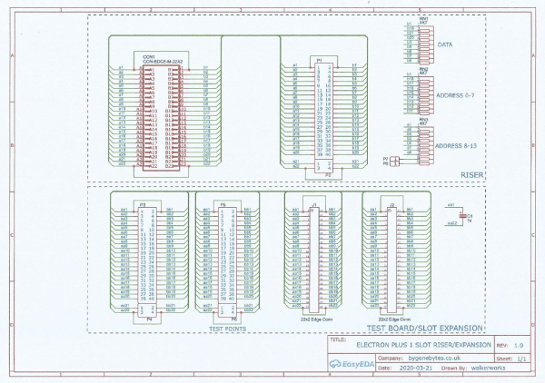


The Slot Riser and the User Port boards have arrived. The Riser plugs neatly into the Plus 1 which gives me room for the three cartidges - the Disc Interface, E2P and the User Port. With this arrangement
of one slot duplicated I had to simplify the EUP by removing the sideways RAM as there would be conflict between that and the E2P. I also removed the serial port - just a thought..this could have been turned
into a MIDI OUT port..something for later..


![]() The Riser BOM, Gerbers and Schematic.
The Riser BOM, Gerbers and Schematic.
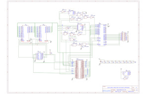
![]() The User Port BOM, Gerbers and Schematic.
Updated to 2021 pcb layout, please see below.
The User Port BOM, Gerbers and Schematic.
Updated to 2021 pcb layout, please see below.
February 2021 - I revisited the Dual User Port PCB to improve the track layout and to finally fit it into a case.


Electron Battery Backed RAM Cartridge (BBRAM8192) - Project on pause.
My original idea for adding the User Port to the Electron was to build an all-in-one cartridge for Stop Press but that was put aside for the sequencer project so now I'm back looking at Stop Press. I had tried
integrating my BBRAM 4096 into the UPURS but this proved impossible for me to get stable so I needed a re-think. I've now had a go and changed the ROM/RAM selection logic and to test it I've made
up a prototype RAM cartridge PCB, if it works reliably I'll be able to load up to 64 ROM images in one cartridge!!
The Plus 1 cartridge slot can decode two ROM/RAM banks, 0/1 or 2/3, this new cartridge has thirty two RAM banks for each Plus 1 ROM/RAM bank selectable in two banks of sixteen using binary switches.
Now assuming this works I'll reduce it to a more manageable size and use 62256 RAMs for the Stop Press/User Port cartridge, 2 x 2 16K RAM Banks. I've got stacks of these IC's from way back when
I made the internal BBRAM module for the +6 so I might as well use them up. Hopefully I'll be able to get Stop Press in one pair and AMX Art and Utilities in the other.

Trackerball and Mouse
When I couldn't find my trackerball I invested in a SmallyMouse2 USB to Quadrature mouse interface to use with a wireless mouse. I've still to try this out as it's for use with the above User Port
for the Electron. Since then whilst searching for something completely different I found my Marconi Trackerball.. see below.. surprisingly it has a 9 pin 'd' type connector on it! It looks as
if I've changed it for reasons I cannot remember so now I'll need to investigate that and see if I can return it to it's original state...and give it a good clean.
![]()
![]()
![]()
![]()
I've given the Trackerball a good clean both inside and out and with the help of Stardot forum members I managed to get the correct connector pinout and now the cable is terminated once
again on a 20 pin connector.
E2P, the Electron 6502 Second Processor
One of my favourite Electron add-ons from the 80's was the Jafa 6502 second processor and I was pleased to see on Stardot that it has been re-engineered and brought up to date. It was the Raspberry Pi
2nd Processor that encouraged me to unpack my Acorn computers last year but I'd like to use the real physical processor for my plan to sequence my synths/drum machines - keeping it as retro as possible.
I have been building up an Electron to do this with a Slogger disc interface/Gotek and now this 2nd processor. I've still to sort out the User Ports as mentioned above..and of course write a program!


When I bought this board a new daughterboard had just became available which replaced the 128K RAM chip for a 512K version that provided seven banks of 64K for languages and one 64K bank as
a ROM filing system, a great upgrade which was well used when writing the Sequencer program. As you can see in the photo above the daughter board protrudes sufficiently to prevent it being
placed in the front slot of the plus one.
I had a little difficulty with getting the E2P stable and it was all down to a faulty component (74LS21) and the 16MHz and PHI0 signals needing cleaned up - something
I'd overlooked (and been reminded of) and dates back to the original E2P.
I initially used a 65C02P3 but after buying a 65C02P4 I managed to successfully increase the operating frequency from 2MHz to 4MHz. Having written a
couple of test programs to soak test the E2P I thought I'd do some speed tests across a few Acorn 8 bit machines to see how they all fair. I used this BASIC one liner:
and here are the results:
| Standard | E2P 2/4/8MHz | 6502 2nd Pro (Wedge) | RPi | RPi 3MHz | |
|---|---|---|---|---|---|
| Electron | |||||
| Electron/MRB | |||||
| BBC B+ | |||||
| BBC Master |
The Raspberry Pi shows how fast a second processor can be and the Electron shows how nippy it can be with it's 2nd Processor. The Electrons archtecture is such that it slows down dramatically when you
move away from Mode 6, for instance, in Mode 2 or 0 the time taken to run the test program is around 18 seconds. This speeds up to 2.57 seconds with the 4MHz second processor but if you constantly
output to the screen then performace tails off as the Electron uses it's own memory to access the screen. One interesting result is that the Electron with E2P is ever so slightly slower when in Turbo mode.
The test systems from left to right:
BBC B+ with Acorn 6502 Co-Pro, BBC Master and an Electron issue 6 with Master RAM Board set to Turbo. The Electron tests were carried out with an E2P with User Ports running at 2, 4 or 8MHz or
a RPi Co-Pro.

Electron Second Processor (E2P) with User Ports
Using the riser board with the E2P and User Ports together works very well but it does look a bit of a mess so I thought I'd see if I could combine the E2P and User Ports together into one cartridge
then it would make for a very tidy solution. I have done a rough layout and it looks like I can fit both onto a board 3.3"h x 7.2"w, this is bit wider than most cartridges but is keeps it at
a reasonable height.
I have finished the board layout and with help from iswasjafa (Stardot) the chip count was reduced by using a second PLD. This PLD contains most of the logic for the User Port and some for the E2P
which made it possible to keep board size within the Plus 1 cartridge slot dimensions - 3.5" x 5.4" a great deal smaller than my original estimate.
One goal with this layout is to try and achieve processor operation at 8Mhz using an 65C816 Module. To this end I have tried to place each component so that the traces are kept as short as possible
(it's always a bit of a balancing act), introduced decoupling capacitors for each IC and used a four layer board so I could use Ground and Power planes. We'll see what happens!
I have looked out all the components as shown in the photo below although I'll probably change a few IC's from 'LS' to 'ALS' types. I am looking at changing the LS245's, LS02, LS14 and
possibly a few others if they are available.
While I'm waiting for the boards to arrive I made a case - just hope it fits! If it does I add the design drawing.
![]() E2P512KUP case design.
E2P512KUP case design.


The assembly of the first board was very straight forward, building up from the lowest components, the resistors to the highest, the IC's. Then testing and fitting in the case.


I then built a second 512K Second Processor using the components from the earlier E2P with daughter board - that board is now in my bygonebytes store. This will give me the flexibility of plugging
it into any slot.
A few days of soak testing at 4Mhz proved both E2P's were running smoothly. The next challenge is to try and increase the clock speed to 8MHz, this goes beyond the capabilities of the 65C02P4 so
I will need to buy a 65C816 to 65C02 module from a2heaven.com.
I now have the 65C816 module:


The results were a bit mixed, the 65C816 module and the 65C02P4 processors work at a 4MHz clock in all four Electrons/Plus 1's I have, The 65C816 module works reliably at 8MHz in three
Electrons, both my issue 6's and the issue 4 but using different link settings! It does not work at 8Mhz in the Issue 2 Electron (No.4).
The Electrons are numbered 1 to 4 at the top of this page so I'll refer to them by number to save space in the tables below.
| Function | Link Name | Link Position | Action | Notes |
|---|---|---|---|---|
| 1PHI0 | J2 & J3 | Buffered | Electron No.2 works with these link | |
| 16MHz | J4 & J5 | Buffered | settings. |
| Function | Link Name | Link Position | Action | Notes |
|---|---|---|---|---|
| 1PHI0 | J2 & J3 | Buffered | No Electron works with these link | |
| 16MHz | J4 & J5 | Un-Buffered | settings. |
| Function | Link Name | Link Position | Action | Notes |
|---|---|---|---|---|
| 1PHI0 | J2 & J3 | Un-Buffered | Electrons No.1&2 works with these link | |
| 16MHz | J4 & J5 | Buffered | settings. |
| Function | Link Name | Link Position | Action | Notes |
|---|---|---|---|---|
| 1PHI0 | J2 & J3 | Un-Buffered | Electron No.3 Works with these link | |
| 16MHz | J4 & J5 | Un-Buffered | settings. |
Running the speed test above gives the expected result of 1.31 second in mode 6 and 1.29 seconds in mode 0:


Elk Tube Elite
A version of Elite written for the Electron with second processor is now available to download on the Stardot forum. The Second Processor could be the E2P, Raspberry Pi 6502 2nd Processor or an Elk emulator. I have no playing ability but it's great to see a program released for the Electron 2nd Processor.


Monitors (and RGB converters)
When I started with the Electron I had a small portable Black&White TV that I used but over the years monitors came and went and what I'm left with now are two Cub Monitors and a KME LCD monitor.
The resolutions of the Cub monitors are standard and medium both giving a good display although due to their size I use the KME monitor. The KME gives a good image but there is one nagging
issue I have with it - when the computer changes screen mode the monitor also changes mode which results in a good few seconds to regain sync and the image also changes position. I can setup the
correct position for each mode but if I change computer then it is different again..a wee bit frustrating..
I have a 13 year old Samsung 19" LCD TV which was assigned to the loft a few years ago that I am thinking about using if I can get the right connecting cables or convertors. The TV has every port you
can think of - Composite, SCART, DVI, VGA and HDMI. I first thought to use the SCART input and bought a cable with the appropriate internal resistors but this gave very unsatisfactory results,
changing modes it would loose sync and only a power cycle of the computer would bring it back.
My next choice was the HDMI input and just by chance a new version of the RGBtoHDMI board was just announced on Stardot so I bought one. As this is based around a Pi Zero I had a bit of a concern over
the supply voltage as it would come from the RGB sockets of the computer. Ordinarily this would be perfect but I use my RGB switch which uses diodes to 'OR' the 5V from each computer so that any
or all will provide the 5V, the downside to this is that the voltage is dropped to 4.3V normally not a problem but my worry was: would it be enough for the Pi Zero?. My research showed that as the
Pi was primarily only using 3.3V or less then for this application it should work OK.
When the RGBtoHDMI kit arrived I built it up, added the Pi with software and right away it worked perfectly. Switching between modes and different computers worked a breeze, I still have to take
the time to set up and store the profile that best suits my machines but first impressions are that this is exactly what I was looking for. It will also work well if I ever get round
to buying a dedicated monitor for the Acorn machines. The next thing to do was to get it boxed and mounted beside the RGB Switch, I ordered the recommended case and some coloured button caps to give it a good looking
finish. The last picture in the group shows the Advanced File Manager (AFM) on the BBC B+.
While I was waiting for the RGBtoHDMI kit arrive I built a small DC-DC convertor board I could fit between the RGB Switch and the RGBtoHDMI just in case it needed the full 5V. It won't be neeed for
this but could be useful for something in the future..
Monitors


RGBtoHDMI


I thought I could add flexibility to my set up by building a ROM cartidge with a built in User Port. I think it may be useful if all cartridges had User Ports!
I took the standard Acorn ROM cartridge design and added in the User Port using 74 series logic rather than the GAL design used on the 512K Second Processor. I'll need to look into
programming the GAL's..
Like the E2P512 I have build a case for the PCB before it arrives..


![]() ROM cartridge case design.
ROM cartridge case design.


ROM cartridge Build.


 ROM cartridge assembled in unpainted and painted case.

 Small production run..
ROM cartridge with User Port Circuit Diagram.
Back in the day I bought a Slogger Plus 2 kit, an addon that attached between the Electron and the Plus 1 and provided two additional cartridge Slots, three ROM sockets, a user port and a serial port.
At that time I reverse engineered the circuit board so I had the circuit diagram in case I had to debug the board once I had built it. My original board has long been sold but now I am
considering resurrecting it in some form. I think the board was originally designed to fit in the Slogger RX case but if you were using it without that case then it wasn't a sturdy fit between the Electron
and Plus 1 as there was nothing to secure it. I lost count of how many times the Electron crashed when I accidentally gave it a nudge...so it had to go.
I could re-work the board and produce a replica but it would come with the same problems as before so I have thought about designing the board either to fit inside the Electron or the PLus 1.
Fitting it inside the Electron is totally impractical as there is far to much electronics for the available space. Fitting it inside the Plus 1 would be possible if I cut out some of the
functionality such as removing the user and serial ports, also the cartridge slots would have to go replacing them with 4 ROM sockets. This effectively gives a board with 7 ROM sockets - so
what we have left is a different version of the AP6! - is there any point in doing this..probably not.

This diagram was drawn using Orcad v3 or 4 and printed using the 6 pen HP 7475A plotter.
Some time ago I bought a small batch of ten 6502A processors, I was just about to install the Slogger Master RAM board and I thought I should have a few spares just in case it went sadly
wrong when I was unsoldering the processor from the Electron Motherboard. As it turned out I had no problem with the install so I had this batch of 6502's sitting around along with a couple of others
that didn't work in the second processor, one was a 65C02P4 and the other a 65C02S8P-10. With all the publicity around fake chips I thought I should have a go at testing them.
Having a quick look on the internet there seems to be a simple test for the 6502 which can show the basic operation of the chip and give you confidence that you can try it in a computer. The test is
the No Operation test or NOP for short which will simply force the processor to count through all its 65,536 addresses on its address bus. To set up the test a few inputs of the 6502 require pulling
high and the NOP code 'EA' or in binary 11101010 needs to be set up on the data bus. Applying power and the processor will read the instruction, increment its program counter and thus the address
outputs, then it re-reads the instructuion and so on producing a binary count on the 16 bit address bus. It does this very fast so LED's on the address outputs will only show the last three flashing, i.e.
A13-A15. An oscilloscope or frequency counter is a good additional way to show the count in action.
I have elaborated on the basic circuit to make it simpler to use by adding a ZIF socket, LED's, a DIL switch on the Data bus to set up the OP code, test point eylets to attach test leads
if necessary, Clock frequency select 1, 2, 4 and 8 Mhz and a reset button. The PCB also has space to mount a frequency counter. The photos below show my breadboard setup and the tests taking place at 1, 2 and 4Mhz and the painfully bad results from the batch,
the circuit & PCB layout and the frequency counter I'll use.
Of the ten 6502A's four I would say are not 6502A's, four are but with various faults on the address lines and two worked as expected - so 2 out 10! not a good result and shows the problem when buying
old processors. I also tried the 65C02P4 and 65C02S8P-10 and I'd say neither are 6502's, from there I tested some known good 65C02P4's and P3's and they passed this test.
The NOP test doesn't tell you the IC will work in circuit but it at least identifies you have a 6502 and that the address and data buses are working.
To make this a useful test rig I have drawn the circuit diagram and ordered a circuit board.


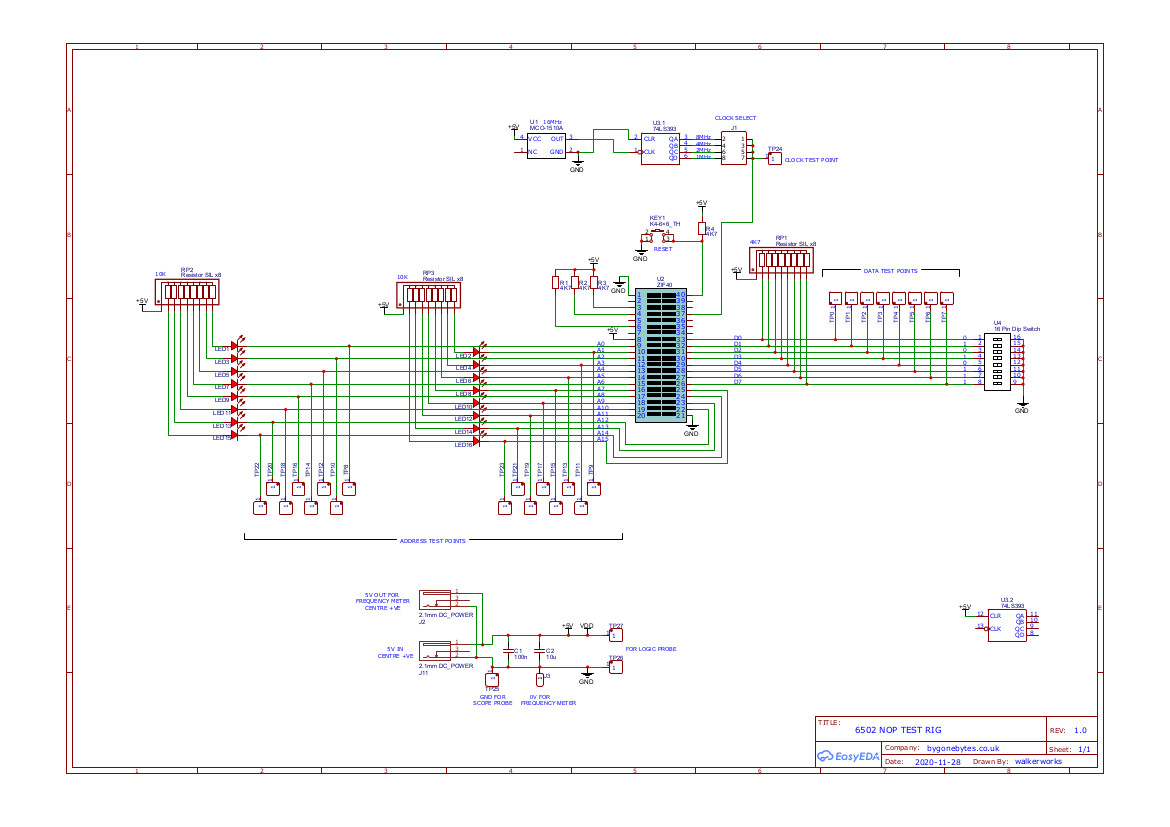
![]() Gerbers files for 6502 NOP Tester PCB.
Gerbers files for 6502 NOP Tester PCB.


A few days after writing up this section my Electron crashed and wouldn't power up properly, the LED was off, no Beeb and the display was an array of coloured rectangles. As the Electron is an
issue 4 my first thought was the ULA needing to be reseated, but that was not the case, I tracked the fault down to the 6502 processor - what a coincidence I had just tested these processor chips
the other day. I selected one of the two good processors found from the above tests, plugged it in and hey presto its back up and running. This little project has paid for itself even before it's finished!
The PCB arrived so I started by assembling the oscillator section and mounting the frequency counter in position, then added the ZIF Socket. I've also looked out a piece of red filter material to
improve the contrast on the counter display.


Testing started with a known good 6502 and as can be seen in the first photo below that all the address lines, as shown by the
LED's, are switching. The counter is connected to A14 showing 31Hz, which is correct for a 2MHz Clock. The second photo shows an oscilloscope attached to A8 showing a nice square wave of 1.953KHz and the
frequency counter confirming this. A logic probe is on A11 again showing that this address is oscillating.
The third photo shows a faulty 65C02 where all the address pins are oscillating except for A15 which is held high (LED off).


![]() Table of Address Frequencies at 1, 2 and 4MHz Clock.
Table of Address Frequencies at 1, 2 and 4MHz Clock.
And to finish off I've mounted the PCB on a plate to protect it while it's in use and can be hung on the wall for storage.


Improvements
As I have been assembling the board I've thought of some improvements that would make the test rig easier to use. Firstly the inclusion of an on board power switch to disable the 5V from the ZIF
socket and secondly, LED's on the Data Bus would have given a clearer indication of the DIL switch positions.
Games and other software
I found in my disc collection the game Crypton, I'd typed in the listing from the September 1988 Electron User Magazine - roughly two full pages!. I normally bought my EU magazine from John Menzies
(now WH Smiths) and you didn't get a cover tape, it was only in the last few months of the Electron User when I subscribed I received the tape so a lot of typing and debugging. I also copied
the Fun School tape and a few other educational programs and created a menu to run all the programs. I see I have 'Kingdom' on the disc, a program from the BBC Welcome disc, which would run ok
with the Jafa Mode 7 Mk2 adaptor.


![]() Crypton and other games..
Crypton and other games..
Another find was a DFS Disc Utilities program I wrote back in 1989, it's really just a front end for the DFS ROM. I wrote it to automate the task of formatting and verifying boxes of new discs - it
could get quite labourious at times. It used the 6502 second processor and Acorns/PRES DFS but it doesn't fully work with the Slogger DFS as Slogger uses *FORMAT instead of *FORM80. I didn't include
a lot of options or make it compatible with other DFS ROM's, so for example, I didn't allow for 40 track discs as I only used 80 track. The display uses MODE 3 and it looks like I wanted it to have
a similar look to some Computer Concepts programs.
Here are a few screenshots:


![]() My DFS Utils..
My DFS Utils..
TV Pattern Generator
About 18 years ago I co-authored a program that would help test CCTV transmission systems and CRT Monitors and it was put to good use. Now I'm revisiting the Pattern Generator program
due to it appearing not to work. This of course wasn't the case as the problem turned out to be a *command clash with a newer Plus 1 ROM.
I did not find this out before I had looked at the software and had re-written parts of it. Looking at the original program we had used an area of RAM below PAGE that was safe to use but my thoughts
were it may be being used by other software so I modified the program to use only main memory from PAGE up to HIMEM of MODE 0. I chose to use PAGE at &1F00 so it will be compatible with the BBC Micro
using ADFS, it was a squeeze but I got it in there.
The program was originally written with the Electron in mind as it has a Black&White composite video output which also influenced the patterns selected - Cross Hatch, Grey Scale black to White, Grey Scale White
to Black, Black Level, White Level, Linearity and Pulse and Bar. On the RGB outut the Grey Scales are Colour. The program is menu driven with each pattern individually selectable or you can select it to cycle
though each pattern. It's very useful if you're repairing a monitor, use of the Cross Hatch and Linearity patterns are both handy for picture alignment.
Here are some photos of each pattern and a few oscilloscope screen grabs along with a DFS disc with the BASIC program and a version in ROM - use *PG to RUN.
![]() The Pattern Generator DFS disc.
The Pattern Generator DFS disc.


Oscilloscope traces:


And in use both in the workshop and on site:


