Introduction
 I recently came accoss the contruction manual for my Maplin 3800 synthesiser and flicking through it I wondered would it be possible to build the 5600s systhesiser today, August 2018,
nearly four decades on.
I recently came accoss the contruction manual for my Maplin 3800 synthesiser and flicking through it I wondered would it be possible to build the 5600s systhesiser today, August 2018,
nearly four decades on.With the passage of so much time there will be a few challenges to overcome namely component obsolescence. Integrated circuits, spring line, patch board, keyboard but to name a few. Please read the 'Hindsight Engineering' section at the end of the page.
On the positive side the build process should be simpler. For me the circuit boards will be easier to produce, no more ferric chloride, bubble etch tanks, spraying copper clad board with photo resist varnish and so on. Just produce the gerber files (I used EasyEDA) and send them off to JLCPCB.
I'm still considering what to do about the patch bay, try to source one or simply bring the inputs/outputs to limited number small jack sockets so they can be 'jumpered' - no room for 900 sockets!
 I am also considering usng the Raspberry Pi instead of a keyboard either as a sequencer
or as a 'soft' keyboard. I will re-hash my sequencer program for use with
the 7" touchscreen and find a space to fit it on the panel.
I am also considering usng the Raspberry Pi instead of a keyboard either as a sequencer
or as a 'soft' keyboard. I will re-hash my sequencer program for use with
the 7" touchscreen and find a space to fit it on the panel.Follow 'What's New' on the top left of this page for quick updates to what's changed on this page.
The new RPi 3A+, just released, is the perfect fit not just because it will run the software easily but it fits neatly on the back 7" touchscreen display. The Pi 7" Touchscreen will greatly enhance the usability of the sequencer once I work through the troubleshooting guide on Raspberry pi website. Hopefully I'll get the right click working and as the screen is optimised for viewing above the horizontal I may need to flip it 180 degrees depending on the final synth panel angle and height.
Designing the boards
The Circuit board diagrams and layouts were reproduced using a Raspberry Pi 3B+/Pi-Top combination with Google Chrome except the Keyboard Controller and Binary Encoder. These two boards were too complex for the Pi to work smoothly so they were produced on a PC Laptop. Auto track routing was also done on the PC as it could be performed locally and not on-line, a much faster method!
There are a few integrated circuits that are now obsolete such as the SCL4416 DPDT bilateral switch and the LH0042 op amp. They can be sourced but at a high cost. I have designed the board layouts where practicable with the original components and placement producing small daughter boards to plug into the appropriate socket.
Designing the front and rear panels
The panel designs were reproduced on the Raspbery Pi 3B+/Pi-Top using Inkscape. The dimensions of the front panel at 36" x 17", slightly enlarged to accomodate the sequencer and the alterations around the patch bay. The panels will be made from a 3mm Dibond material, two aluminium sheets sandwiching a polyethylene core, with white background with black text.
As I suspected from the start of the project getting hold of a 30x30 matrix patchboard would be very difficult so I looked at several other ways to implement the functionality:
(1) Use 3.5mm jack stereo jack sockets and wire them so when using a mono 3.5mm jack plug it would short out the cross connection. This would involve 900 jack sockets wired in a grid.
(2) Analyse how I would use the patchboard and work out the most flexible way of patching the outputs to inputs with the minimum amount of 3.5mm sockets. I came to the conclusion that each output should have four sockets and each input two. Patching out to in would be via short patch cables just like todays modular synths.
(3) Use bilateral switches such as the CD4016 and use push buttons to select the patch.
I opted for the reduced patch board, option 2, as it is the simplest to implement.
Some hindsight - There is a lack of clarity where the Sync switch should be placed. The manual shows in Fig 13, and in the panel overlay on page 3 that the switch is mounted between the Range and Tune controls. It also shows on the photo on the front page, the photo on page 5 and the photo of oscillators 2 - 4 on page 17 that the switch is between the Tune and Free Run controls. Whilst assembling the panel I noticed I drilled the panel one way and the mounting brackets the other! So obviously the panel layout wins out!
I have two options for the rear panel design and they only differ in their physical size. The large one is due to my chosen supplier having a minimum dimension of 6".
The panel build is documented further down the page..


Making the project public
Each printed circuit board and panel design has associated CAD files which I will release when I have fully tested each one. As I release each one I will add a link to the EasyEDA project page to each secton below. Note - I have not yet cross referenced the BOM (Bill Of Materials) on the EasyEDA site to the Maplin Synthesiser construction book so care should be taken when selecting components and their lead spacing. Particular attention should be paid to the capacitors as I have updated most of them.
But if all you are interested in is the Gerber files to produce your own circuit boards they can be found here..
Boards in order of build
Power Supply - EasyEDA Project Page.
There are two transistors on the power supply board that are obsolete, the MPS3638 and the PN3643, these were replaced with 2N4403 and 2N4401. The Power Supply is now ready to use in the testing of all the other boards.

Oscillator x 4 - EasyEDA Project Page.
It is the same issue of transistor obsolesence on the oscillator boards, the MPS3638A and the PN3643 were changed to 2N4403 and 2N4401.
One other change I am made and it is purely down to cost and that is to use 6 way switches for the range selection reducing the range by two settings. The wafercon switches are still available from RS Components but at about £30 each. Maybe towards the end of the project I might change them.
As pcb space is saved using a double sided board I added the preset board on to the end. It doesn't need to be used as the connections are still available to use the separate board.
The oscillator uses a SCL4416 bilateral switch which luckily I have one left over from by 3800 build 40 years ago! For the other three oscillators I'll need to come up with another solution.
The oscillators are taking shape, all four boards built, tested and set up.


March 2026 - I have just recently added a proper keyboard and I'm looking at finishing the case but before that I still have one part to complete and that is the Range switch for the oscillators. At the time of building this, around 2018, I couldn't find an affordable 2 pole 8 way switch so I used a 2 pole 6 way switch and sacrificed the use of the LOW and 1/2' positions but now I think I have found one that will do the job.
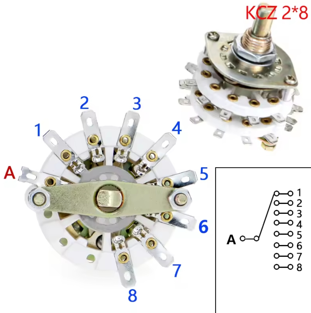
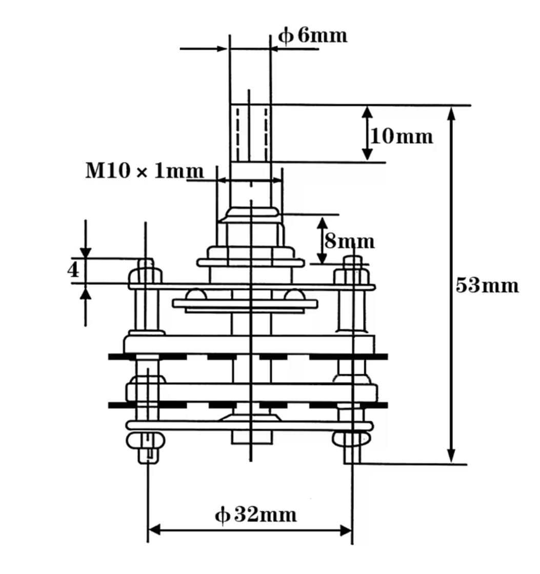
I have ordered these from Aliexpress and hope they're not to big to fit in the space.. I'll add some photos of progress.
Below is the line up of switches considered, to be used and temporarily used.
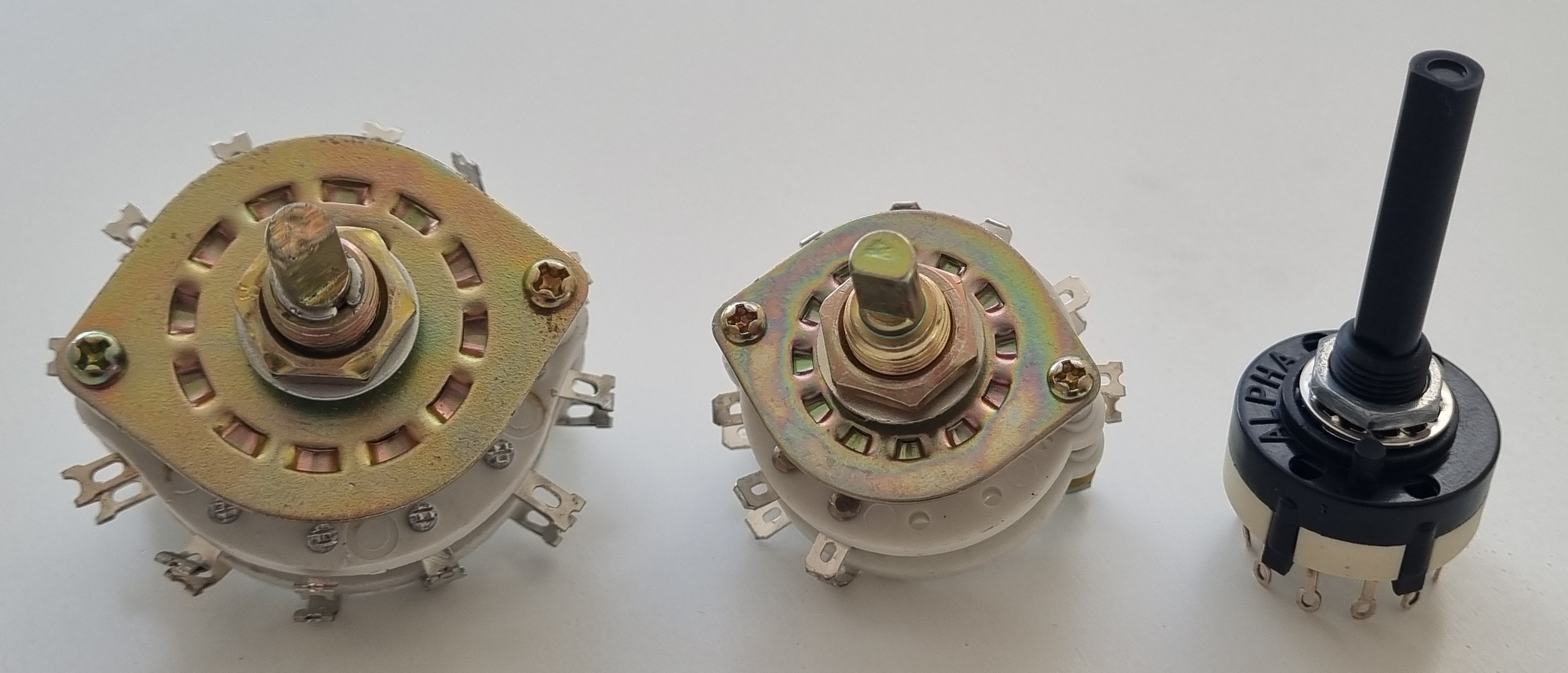
On the right hand side is the 2 pole 6 way switch that I have currently installed, on the left was the switch I bought six years ago and found that it was a bit larger than expected and the new one in the middle which by size is also in the middle.
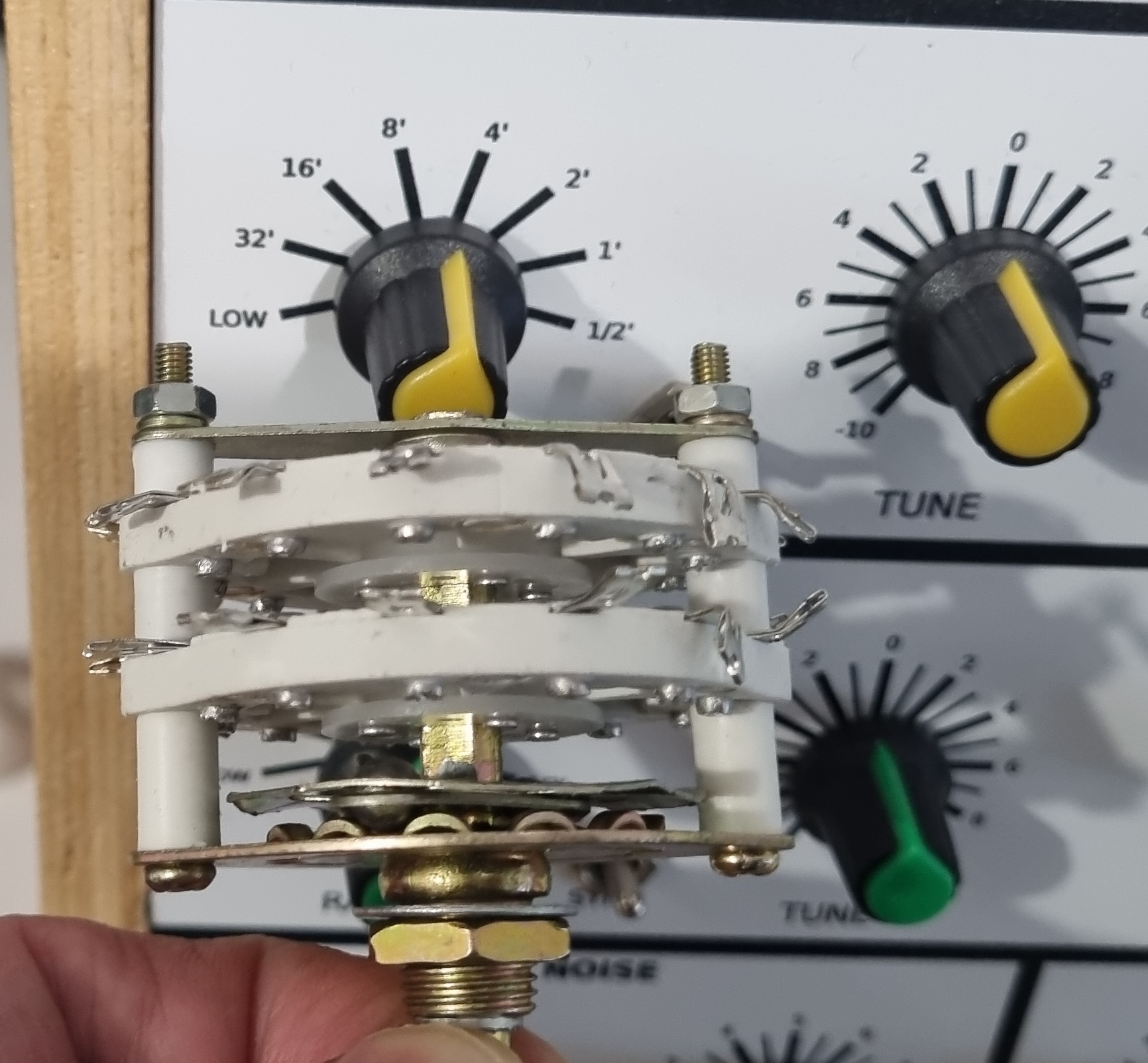
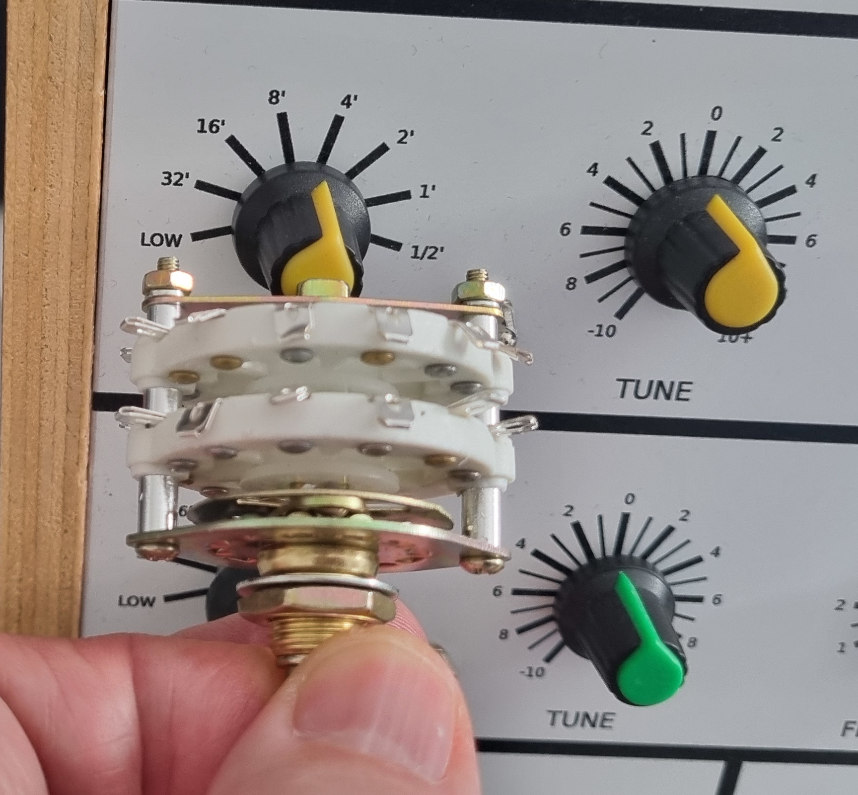
As can be seen the large one was just not going to fit, hence, I'm using the six way switch...but the new switch looks as if it will just fit so on with the changeover.
Mixer - EasyEDA Project Page.
Photo:
(1) The Mixer board is complete with only two changes, the BC108C is now a BC107 and the BC178 a BCY70.
(2) and (3) The board and potentiometers are mounted on the aluminium plate and wired, I'll tree all the wiring once the synth is built - just in case I need access to the wiring or board before then.
(4) Testing is now finished and it works well.


Pseudo SCL4416 - EasyEDA Project Page.
The SCL4416 Quad Bilateral Switch is quite tricky to get hold of and at a reasonable price. I therefore made a small board that is functionally equivalent from a CD40106 and a CD4016 and at a fraction on the cost.. and works a treat.


Keyboard Controller - EasyEDA Project Page.
The LH0042C is obsolete so I made a small change to the board for IC 16 and 17. The pinout is changed from a TO99 to an 8 pin DIL which will allow a greater choice of replacement including using a TO99. I will be using a TL061.
When making the PCB for my 3800 synth I found a mistake on the circuit diagram so I was aware of it this time around. The voltage ladder resistors R38, R40 etc. should be connected to 0V. see photo below.
The testing is complete and it's working OK. I had a number of faulty RC4136's, the lead lengths are too short - see photo. I need to order a new batch and replace them.


Keyboard Controller LED Strip - EasyEDA Project Page.
To simplfy the wiring of the keyboard controller LED's I've added this small board.
I'll be using white LED's throughout - That decision is now reversed! Probably not the best idea to have white LED's on a white panel! They will now be red flat top 3mm LED's.


Sample and Noise - EasyEDA Project Page.
The issue of transistor obsolesence is as above, the MPS3638A will be changed to 2N4403. The PCB is now fully tested, the photo shows a temporary dual gang pot which allowed me to complete the testing.


Transient used in Envelope - EasyEDA Project Page.
The issue of transistor obsolesence is as above, the PS3638A will be changed to 2N4403 and the PN3643 to 2N4401. I have also found it difficult to source RV7, a 2M ohm double pole switched potentiometer so I have made a conversion board - see below.
Testing - the board is fully tested but what came to light is an issue with the 2M switched potentiometer I bought. The only pot I could source has two solder tabs and when switched on measures the full resistance, turning it further it reduces to zero ohms. This means that in use when the pot is fully anti-clockwise it is at maximum delay and reduces when turned clockwise. This goes against the calibration on the panel! It works and will do for now but I am on the lookout to replace it. If this type of pot has to be used I would alter the calibration on the panel CAD file.
Note - The VCA used in the envelope generator is the same one used elsewhere in the project and thus has that silk screen. Use the manual to cross reference the component parts for placement or make a separate board with an update silk screen.
Update - I have managed to find some 'vintage' 2m2 switched pots so I have fitted one to the Envelope and Transient circuits. This means that the 1 pole to 2 pole switch board below is not required.
Converting 1-pole switch to 2-pole switch - EasyEDA Project Page.
I no longer need this board as I sourced a suitable switched pot but I'll leave the details below as it may help someone in the future.
The Envelope board requires a 2M ohm potentiometer with a 2-pole switch which I have found impossible to get. I did manage to source 2M ohm single pole potentiometers which are also used with the Transient boards so I designed a simple board to convert the potentiometer switch from 1-pole to 2-pole.


Voltage Controlled Amplifier (VCA) - EasyEDA Project Page.
No changes were made. Both amplifers have been tested OK.


Transient A/B - EasyEDA Project Page.
Board complete and assembled. I cannot source RV1 a dual gang 2M ohm pot! The best I can find is 1M ohm version, if I use this it will affect the timing of slope 2 and the retrigger. I could accept this limitation or I could double the capacitance of C1 on both the transient and retrigger boards and reduce RV2, slope 1, to 1M ohm.
Update - After making enquires all round the world I eventually found a 2M dual gang potentiometer in Chesterfield! It is 'vintage' which I suppose fits the theme... I'll hopefully get that soon and get it wired along with the Retrigger board, then the boards will be ready for testing.
Photo 7 - Part wired Transient/Retrigger boards with Transient B under test. Transient B is now tested and set up.
Photo 8 - Transient B/Retrigger wired with 'vintage potentiometers' ready for testing.
Both Transient boards are now tested and mounted on the panel.
Retrigger - EasyEDA Project Page.
Board complete, assembled and tested. No changes were made to the components.
Reverb and Phase - EasyEDA Project Page.
Board complete, assembled and tested. Q1 will be changed to a 2N5320 and Q2 to a 2N5322. The original reverb tank is no longer available so I will use the Accutronics Blue Reverb AMC2BF3. The 2N3819 FET's are available in two pinouts both in TO92 cases, the one I've used is the Fairchild version.


Voltage Controlled Pan and Ancillary - EasyEDA Project Page.
Board complete, assembled and tested. Q1 will be changed to a 2N4401 and Q2 to a 2N4403.


Voltage Controlled Filter (VCF) - EasyEDA Project Page.
Board complete and assembled. Once again the transistors were changed to 2N4401 and 2N4403.
(1) adnd (2) PCB artwork ad different stages of production.
(3) Blank PCB.
(4) PCB assembled.
(5) Both VCF's built but awaiting a few components.
(6) Both VCF's built and tested.


External Inputs - EasyEDA Project Page.
Board complete and assembled and tested.


Joystick - EasyEDA Project Page.
Board complete and assembled.
This board has been tested and working OK.


I have not been able to track down the original 4-axis joystick (only 3 axis used) or a direct replacement so I have made the decision to use a 2-axis joystick for the vertical and horizontal outputs on the patch panel and a slider potentiometer for the pitch bend.


Headphone Amplifier - EasyEDA Project Page.
I am thinking a 5 to 8 Watt amplifer is a bit of overkill for headphones so I have used the LM380 2 Watt amplifier instead. The amplifiers no longer need to sit near the transformer and can be mounted on the panel. I don't believe a heatsink is required as the dissipated power is much lower and will be dispersed via the ground plane on top and bottom of the PCB. Mounting the 6.35mm jack socket and the potentiometer on the PCB involves sinking the jack socket into the board to get them to line up..
Testing - after a few hours soak testing at a reasable volume the LM380's did get warm so I decided to put some heatsinks on. I had a pile of Raspberry Pi heatsinks so I fitted them and now they get warm so they must be doing their job. This was the last board to be fitted to the panel so everything is now ready to fit in the case..see below.


Binary Encoder.
Board complete, assembled and tested - EasyEDA Project Page.


The original Binary Encoder.

Binary Encoder under test. I remember testing the original one when I found a key would always return a wrong code - the fault was a diode with the band at the wrong end!!
While testing this one I found twelve inputs which didn't reliably trigger - increasing the Cx capacitor to 18nF fixed the issue.

Test Keyboard - Circuit & Gerbers
To simplify the testing of the Keyboard Encoder and the Keyboard Controller I knocked up a simple 48 micro switch keyboard. To keep everything clean for the final wiring it will be connected to the keyboard encoder using jumper cables.
I kept the cost of the PCB to $2 for 10 and designed the board with seven keys with the same spacing as a full size keyboard. Eight keys per board would have been better but after all it's only for testing..

2026 - I have finally built a proper keyboard for the synthesiser by repurposing an old Yamaha PSR27 keyboard. The project starts from finding an old broken Yamaha PSR27 but still having an unmarked keyboard to getting it fitted and working in my synth...it took a while :)

Raspberry Pi Interface - EasyEDA Project Page.
The design for the Raspberry Pi interface is complete. It allows control of the synthesiser in the same way as my Maplin 3800 sequencer with the addition of 8 input data bits which will allow a recording functionality to be added. The board is just a simple Low-High/High-Low voltage level shifter. It converts the signals to/from the Raspberry Pi 3V3 and the CMOS 14V logic.
The board is assembled, tested and mounted on the Pi 3A+.
Photos:
(1) and (2) PCB artwork at different stages of production.
(3) Blank PCB.
(4) PCB assembled.
(5) Interface being bench tested prior to fitting to Raspberry Pi.
(6) Interface fitted to Raspberry Pi 3A+ and the Touchscreen.
(7) Interface voltage level shifting being tested - no burnt out Pi!
(8) Frame added to screen to simplify mounting to faceplate - the rear of the screen is nice and flush.


When the Interface board is assembled and tested it'll sit on top of the Raspberry Pi - see above. Full software for play/record sequencer is now written and bench tested awaiting the Binary Encoder and Keyboard Controller boards to be tested
(1) Switching on the Raspberry Pi 7" Touchscreen for the first time and running my Maplin 3800 sequencer program.
(2) The Touchscreen with the Raspberry Pi 3A+ mounted on the rear of the touchscreen.
(3) My first pass at rearranging the screen layout to fit the 7" screen.
(4) Screenshot of my first pass of the sequencer screen layout.
(5) Screenshot of finalised sequencer screen layout.


 Sequencer script (just copy & past into IDLE 2.7).
**UPDATE 2024**
About 6 years have passed since I wrote the sequencer script and Python 2.7 has more or less disappeared so it's not as easy to create a working SD card as it used to be. I have taken an image of my SD card to simplify the creation of a bootable card.
Just use you favourite image program, Belina Etcher, Win32Imager etc., 8Gb cards or greater should work although I have only tested with a 16Gb card. Insert it in you Raspberry Pi and switch on, the sequencer program will automatically load.
How to work the sequencer:
Set up the notes you want by setting the binary code check boxes, if you do not want to use all 96 then select the Halt check box next to your last note. The binary codes and Halt check boxes can be changed while the sequencer is running.
Select the time duration between each note in 0.025 second increments with the SLOWER/FASTER buttons. If you want to change the delay between each repeat then set the time with the Longer/Shorter buttons in the Loop Control area, again in 0.025 second increments.
In the Loop Control area select the check box INFINITE LOOP if you want notes to play in a continuous loop or if you want to select a preset number of loops switch off INFINITE LOOP and use the MORE/LESS buttons to set how many times you would like it to repeat.
Selecting the Tempo << / >> buttons steps the Tempo times slower or faster from note 1 to the checked Halt/Repeat box in 0.25 second increments.
Touch the START button to begin the sequence. The position of play as the squencer is running is shown by the note number being highlighted in blue.
Touch the STOP button to stop the sequence. On restart the sequence it will start from the beginning.
Touch the CLR button to remove all selected notes, Halt, Repeat check boxes and Loop Times.
To Record a sequence from the keyboard:
As I used dedicated GPIO pins for the input and output data there is no need to use the computer switch on the front panel.
Touch the REC button. Recording does not begin until the first keyboard key is pressed. As you play the binary code for each note will be displayed along with the time from the previous note next to it.
Touch the STOP button to stop recording and a HALT is automatically added on the last note.
Touch CLR button to remove all selected notes, Halt, Repeat check boxes and Loop Times.
To Save or Load a Sequence:
To save a sequence go to the menu bar and select File/Save As, a dialog box will open for you to name your file. Click Save to store your file. The default file extension is .seq
To load a previously saved sequence go to the menu bar and select File/Open, a dialog box will open for you to select a .seq file. Once selected click Open and your sequence will be restored.
All the controls, START, STOP etc. are also in the menu system.
The problem I have found with todays potentiometers! - EasyEDA Project Page.
It seems in todays world it is not possible to get every potentiometer for this project from the same manufacturer or indeed in the similar ranges. Some of the switched potentiometers I am using are small PCB types and require to be mounted securely on a small board..So I made one..


Maplin 5600s Front Panel
(1) The front panel has arrived and my first thoughts are the image could be sharper, it is OK but could be better. I'm looking to see where the issue lies in the printing process.
(2) Tidied up a space on my bench to assemble the panel and seeing what the panel will look like with all the knobs placed in their positions. I spotted a mistake with the Foot Switch text - very annoying! The word 'READ' has been corrected to 'GATE' in the svg and pdf files.
(3) and (4) The front panel re-printed- text fuzzy and nice and sharp. - The issue was the speed of the panel going through the printer.
(5) Panel drilling and cut-outs finished.
(6) The panel assembly begins.
(7) and (8) Panel with the Patch Sockets, Oscillators, Mixers, VCA's, VCF's, Envelope, Sample and Hold, Transient A and B, Retrigger and External Inputs board mounted - also some switches and LED's.
All the panel mounted boards are now in place and are individually tested OK. With my change to the Headphone Amplifier that was the last board fitted to the panel. There are only a few boards left to test, Keyboard Controller, VC Pan, joystick and Reverb. They all fit on the base of the case so it is time to concentrate on designing and building the box.
The final pots and switches have been added so that's the front panel complete..I've even put on all the knobs. I've updated the front and rear panel photos for the last time.


Maplin 5600s Rear Panel
(1) The Rear panel has arrived and has the same issue as the first print of the front panel - the reprint is nice and sharp..
(2) Rear panel drilled.
(3) Rear panel with sockets mounted.


The Case
I am building the case from 12mm plywood and will be similar in design and shape to my Maplin 3800 synthesiser. So I have to turn this..

into ...

The Panel Fitting.


I'm going to do as much wiring on the PCB's, rear and front panels as possible before I bring them together. I'll update the photo(s) below as the wiring progresses.


The wiring is almost complete, I have terminated the Raspberry Pi I/O on the Keyboard Controller and the 230V on the panel switches. My strategy to powering everything up will be to do one or two boards at a time starting with the Keyboard Encoder and Controller, from this I should be able to check all the keyboard codes and the Raspberry Pi Record and Playback features. The Mixers will be next then Oscillators and so on until it's all up and running..
The start of the power up!
I have powered up the first two boards, the Keyboard Encoder and the Keyboard Controller. Using my makeshift keyboard I've been able to test the basic functionality of each board and the Raspberry Pi sequencer software.
The second step was to power up the four oscillators and the mixer. All good so far..and after 10 months sound for the first time!
The third step was to power up all the other boards and to start testing each one. The video shows the sequencer running through a recording of the keyboard 48 notes, the sound is generated using oscillators 1 and 2 controlled by the envelope and the low oscillator fed through a VCF. The key presses have a touch of glide added. Problems found so far are the Glide on/off and the Glide/Gate switches are wired backwords! was it me or the book..still to find out. A lot more to test in the coming days..
After comparing the circuit and panel wiring diagrams and cross referenced the panel labelling I came to the conclusion that the panel wirings were at fault, I have marked up the correct switch numbering on the circuit diagram. see below. I have swapped the wiring on both switches and it now works perfectly.


June 2019, Just finished setting up the Keyboard Controller and powering up the Headphone Amplifier. That's the Synthesiser more or less complete, I just need to tidy up the internal wiring and sort out a better keyboard/or cover. That's it all working...so it was possible to build a 40 year old synth albeit with a few tweeks such as the patch panel (changing to sockets turned out quite successful) and keyboard.

Two Maplin Synths..


Here's a video of the build:
Hindsight Engineering.
This is the point where I can look back over the build and reflect on the project and my decisions throughout. The first decision was to recreate the synthesiser as accurately as I could knowing that it is an over forty year old design. This decision almost fell at the first hurdle but I carried on and tried to minimise the changes throughout the project.I made a good start with the power supply with simple substitution of some transistors. Although I found I used a wrong pinout in the Easyeda library for one of them. My error was not checking the accuracy of the part - a lesson learnt there! It was easy to correct by rotating the transistor on the board. (Gerbers have been corrected) The other change I made inadvertently was to have 15 connectors instead of sixteen - I followed what I'd done on my 3600 and not the book, I didn't take into account that there are many more boards in the 5600! In the end this did not turn out to be a problem as with carefull wire allocation I still have one free position. Interestingly plug allocation is not given in the manual.
At this point I came face to face with a cost/functionality decision which was with the oscillators, my first conscious deviation from the design. The 8 way frequency range switch now cost £30-35 each, for four £120 - £140, an amount I didn't want to spend straight away. The lure of 6 way switches at £1 each was compelling and I thought I could easily change them later if required. This decision lead to a change in circuit board design layout as it wasn't possible to mount the preset board on the back of the switch. I designed the oscillator board with the addition of the presets and kept it the same length as the original, I also made it possible to use the board with or without the presets - thus the board can be used as spares for the original.
The design of the Maplin synthesiser is quite exceptional with using only very popular integrated circuits but with time obselesence has caught up with a few. The first one I came across was the SCL4416 quad bilateral switch. I have quite a collection of IC's from the 70's onwards but only had one of these and searches on the internet didn't come up with any sensible results. The 4416 is an easy function to reproduce with a 4016 and an invertor so my next design decision was do I incorporate the change on the board or build a daughter board. I chose the daughter board option as it kept the original board design for anyone who has a collection of the 4416 IC's - flexibility..
Potentiometers - this was tricky as a few pots in the design were very hard to source - basically any above 1meg ohm. Pots with switches even harder! I ended up using a variety of makes, shapes and sizes even down to sourcing some vintage ones. Some of the old pots sourced through ebay worked for a few turns then failed. I ended up emailing a few suppliers I found in the Practical Electronics magazine adverts and got lucky.
The Panel - First time round with the 3800 I made my own panel, buying one for £11.98 was way too expensive. Back then I had a workshop at my disposal for cutting, drilling and painting the panel. I used Letraset for the nomenclature. Now with a limited workshop and Letraset a thing of the past I had to look for alternatives. My first thought would be to find a company that would supply the finished panel to my CAD design. The quotes for an aluminium, drilled, painted and silk screened ran into several hundred pounds. I eventually settled on a road sign supplier! for a fraction of the cost..although I had to drill it myself. The reason why it is white, is that it is the base colour of the panel, I thought if it was printed black it would show uneven shading across the panel.
Matrix - the next deviation from the design. Sourcing a pin matrix is tricky especially one 30 x 30 pins. I could find old adverts selling them for £200 or more but none available today. Even smaller versions seemed elusive so I settled on using 3.5mm jack sockets. One option is to use 900 stereo sockets in a matrix of 30 x 30, then use mono plugs as pins but space ruled this idea out. Looking at the design it was obvious that this was the fore runner to modular synths so I decided to make a simple plug patch bay. A major benefit to this setup is extracting and injecting signals that you couldn't do before.
Sequencer - The Maplin sequencer that accompanied their synths was Z80 based with the code is being very elusive...so not easy to replicate. I had designed a sequencer based on a Raspberry pi a few years ago for the 3800 so I thought I could build that into the 5600 with some modifications. I bought a 7 inch Touch screen, re-wrote the software to suit and added a recording function. I'm happy with how it turned out.
Keyboard - The keyboard remains unfinished as I cannot find a similar contact block and keys system. I am looking at picking up an old defunct 'keyboard' from around that era to see if it uses a similar diode matrix interface and if lucky convert it to work with the 5600. At present I am using a makeshift keyboard made from mouse micro switches, unplayable but great for testing. Unplayable because they are tactile..they click when pressed.
With hindsight what I would do if I started again?
First thing I would do is not to stick to the original design, far too much wiring..I must have use around 100m of cable!! So I would reduce the wiring substantually by update all the circuit boards to have as many pots mounted directly on board, this would also remove the need for aluminium brackets. Moving jumpering points on the PCB's closer to where they need to be wired, would save some wire and also on all the PCB's I'd bring the power supply terminals together so plugable terminals could be used. I would also combine a few boards such as the retrigger and transient envelope and the envelope and VCA. Using more and smaller dc power connectors on the PSU would be more practical.
The keyboard controller works by producing a different voltage for each key pressed similar to todays 1V/octave so it would be possible to interface a midi to cv converter then it opens up the use of any midi controller/keyboard. I have been looking at two different midi interfaces for the Modular synth I've been building, one of which will suit the 5600. The midi interface published in the Practical Electronics magazine Febuary to July 2019 I think fits quite well with the 5600 having a maximum of two cv outputs and is designed for a mono synth. The other I will use with the Modular synth is the Midimuso cv-12.
All boards, CAD and software are available for anyone to download and modify to their hearts content. If anyone does make changes please let me know, I'd like to see how it all developes.
Above is my blog of events, decisions, errors I've found etc. written over the period from August 2018 to June 2019.