Introduction
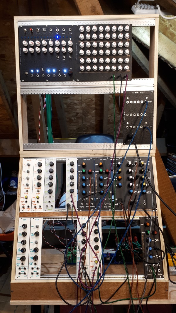
This new project (March 2019) will bring a lot of the elements of an analogue synthesiser into the small Eurorack format.I will concentrate on the following basic Modules:
- A +/-12V Power Supply with distribution.
- Clock/Sequencer.
- Voltage Controlled Oscillator(s).
- Voltage Controlled Filter(s).
- Envelope Generator(s).
- Noise Generator.
- Voltage Controlled Amplifier.
- Echo Unit.
- Mixer - Pan to Stereo.
- Low Frequency Oscillator.
- Sample and Hold.
- Midi to CV/Trigger.
- and...
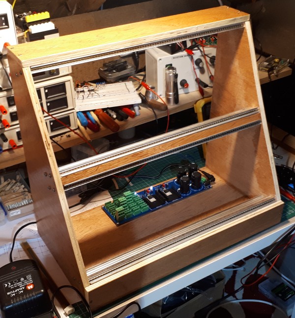
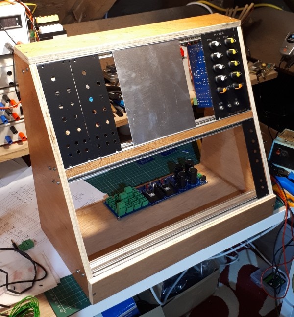
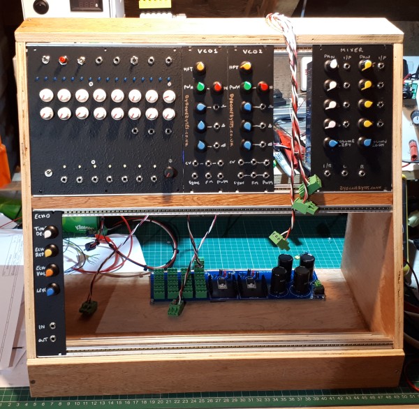
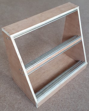
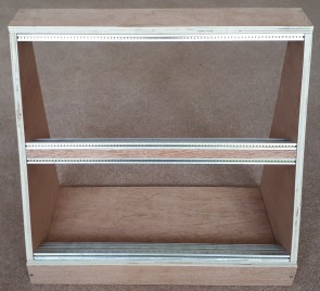
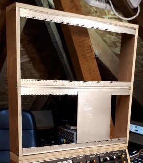
I am going to use an old recovered 6U rack that I've had lying around for years. The 6U rack was configured with two rows of 3U, ideally I'd have use the rack as is but at 3U it's just a bit too small for all the pots and sockets that's going on the front panel of each module. I took it apart to re-use the front extrusions with wooden sides to form a dual 4U rack. The wood is just off-cuts from the Maplin 5600 case.
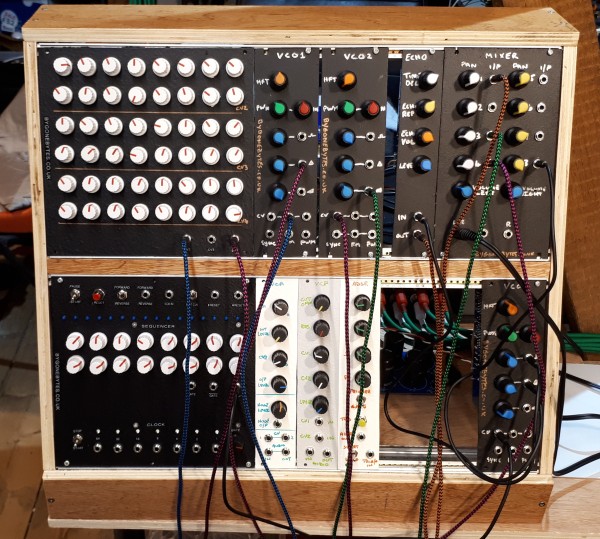
It didn't take long for the quantity of modules to out grow the rack so I have built an extension using the rear extrusions.
The PSU
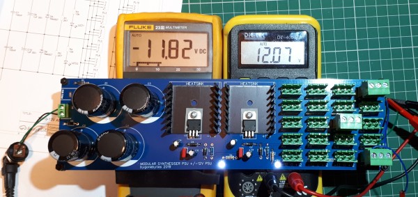
I have built many power supplies over the years and could have used any one of them but I liked the simplicity of the design in the March 2019 edition Practical Electronics. I just modified it by adding a couple of LED's and twenty +/-12V sockets to feed the modules.
The Clock/Sequencer
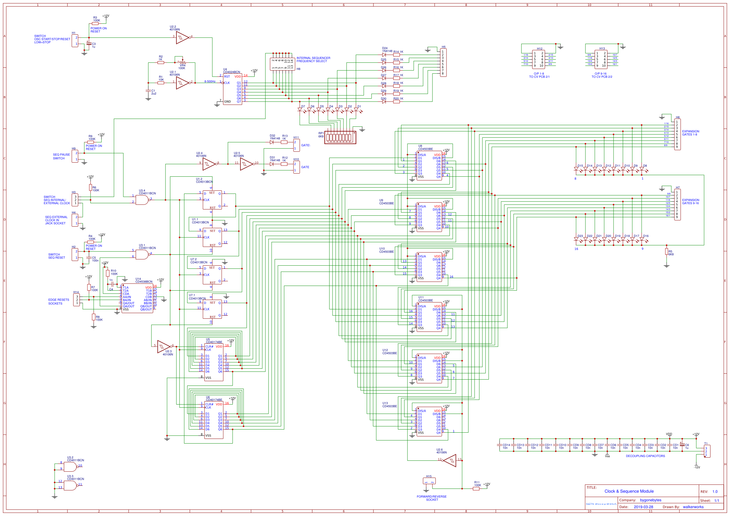
The first task was to define what I wanted the clock and sequencer to do. The obvious functions were to provide a Gate and a Control Voltage (CV) over a defined number of steps. I then thought about all the frills I'd like such as how many steps?, how many CV's?, how many Gates?, should the sequence be reversable?, when should it loop to the beginning?, should it sync to an external clock?, what should trigger all these events - switches, external Gates/Triggers? and so on. Once I'd answered all these questions I had to decide how I should implement all this functionality - software or hardware. Software is the obvious answer as it would be easy to add and alter the functions although I'd probably need to use one or two Arduinos (or similar) rather than a Raspberry Pi as it would have to power up quickly and not be susceptible to corruption when cutting the power. I also didn't want to use a screen or have a shutdown sequence. The other option of using CMOS 4000 series was however more appealing, I'd had some experience back in the 80's of using both 74 and 4000 series logic and in some way that by using it it'll fit in with the bygonebytes theme..
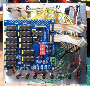
The first area to tackle was the clock. For this I used a simple Schmitt invertor circuit, U2.1, to produce the square wave with a potentiometer in the feedback to provide the variable frequency. However this wasn't enough, I wanted to have multiple Gates available with 1/2/4/8 etc. division so I used a CD4024 7 bit binary counter, U4. The outputs of U4 have LED's so I can see when each Gate is turned on. I also added an internal header, H8 to select the internal frequency for the sequencer. A Start/Stop switch is connected to H1 to hold U4's reset to enable the count.
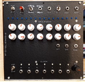
I made my decision that the sequencer should have 16 steps so that ruled out the common CD4017 decade counter which has 10 outputs so I implemented the count with D type flip-flops. Using two CD4013, U1 and U7, and two CD40174, U5 and U6, gave me the 16 outputs needed. The sequence is paused using a switch. The clock source, Internal/External, can also be selected via switch. Resetting is achieved via a push switch or via Gate/clock pulses. By selecting the appropriate Clock pulse the sequence can be looped at 2, 4, 8 and 16 steps. Each step is displayed on a blue LED.
Next was how to make the sequence reverse..I cheated a bit here as it's not easy to reverse a decade counter..so I used six CD4503 hex tristate buffer IC's, U8 to U13, to swap over the outputs from the counter. 1 to 16, 2 to 15 etc. This function can be selected via a switch or by using the clocks.
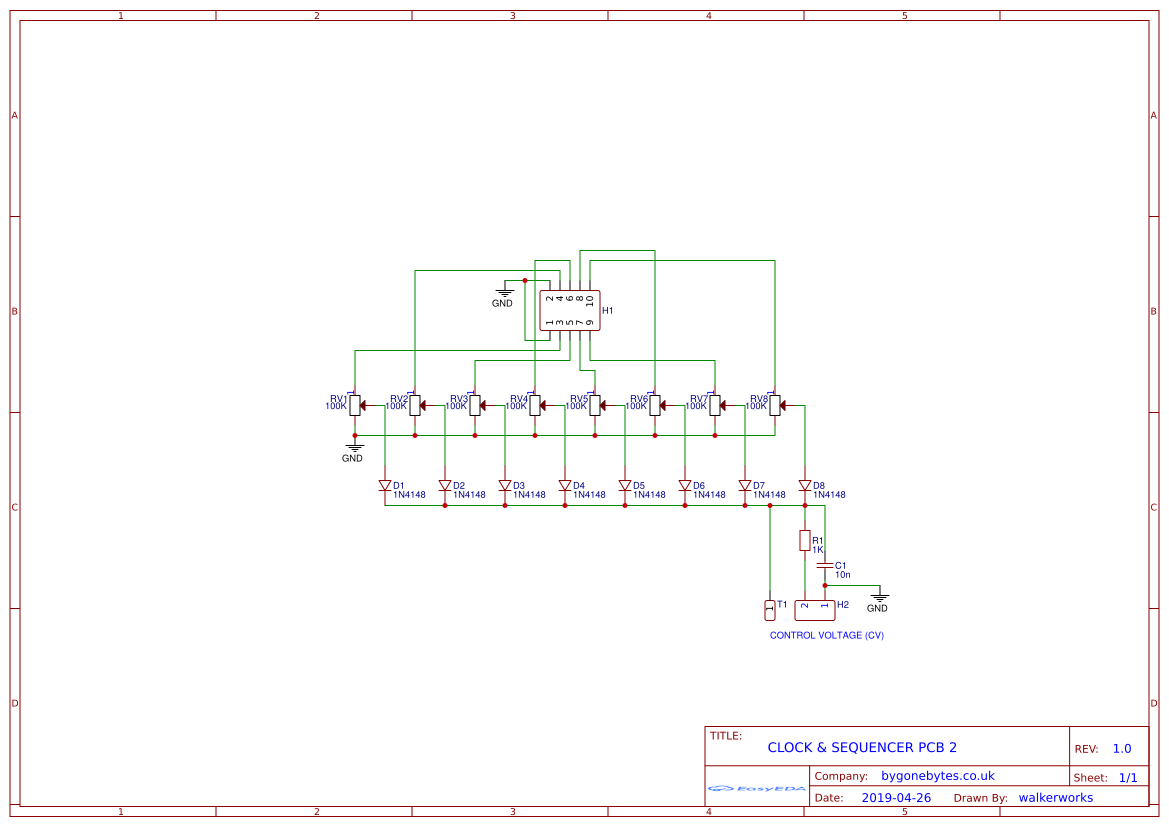
Finally I decided to provide four CV outputs so multiple sounds can be triggered on each step of the sequence. To do this I diode or'ed the 16 step outputs each through their own potentiometer to set the step voltage level.
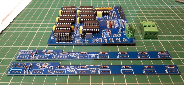
As this was something I dreamt up myself I built each part of the circuit on breadboard to show to myself that it would work without any glitches. Then it was off to JLCPCB to manufacture the circuit boards. I managed to keep the main pcb to within the 100mm x 100mm limit for the $2 for 5 boards but for the CV boards there was no choice but to go longer.
During the final board testing I found two issues, the first I soldered in a diode the wrong way round (can be seen on the photo) causing some weird effects. The second is that I failed to take into account that when using the clock outputs to switch forward/reverse via the patch sockets the series protection diodes would prevent the inputs from being pulled to ground. The simple answer was to take them out of circuit by soldering a dip switch accross them. Again this can be seen in the photo. If I assemble a second sequencer I would simply use wire links.
So the functionality turned out to be:
Variable Clock, Clock - 1/2/4/8/16/32/64 outputs, 16 Steps, 4 CV outputs, Sequence forward or reverse, External clock can be used, Loopable at 2, 4, 8 and 16 steps, Gate and NotGate.
VCO - Voltage Controlled Oscillator
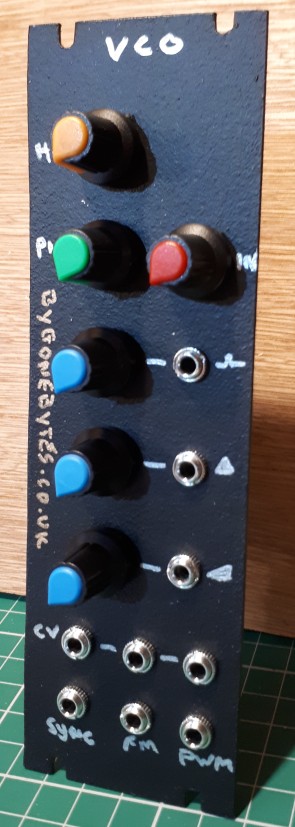
The VC Oscillator is based on the CEM3340 data sheet and modified to suit my needs.
VCF - Voltage Controlled Filter
The basic circuits for the VCF is from the March 2019 edition of Practical Electronics.

ADSR - Envelope Generator
The basic circuits for the ADSR is from the May 2019 edition of Practical Electronics.
VCA - Voltage Controlled Amplifier and Noise Generator
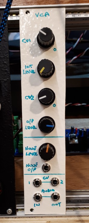
The basic circuits for these are from the April 2019 edition of Practical Electronics.
Echo Unit
The basic circuits for the Echo unit is from the April 2019 edition of Practical Electronics.

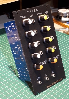
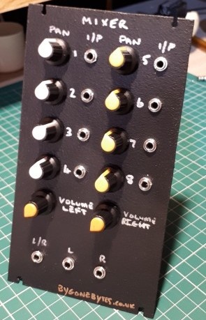
Mixer
The Mixer circuit is from my Mixer design build in the late 70's.
Midi Interface
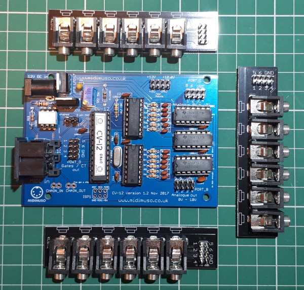
Way back in the early 80's when the MIDI standard was being introduced I couldn't believe the decisions being taken with regard to the physical interface, current loop!, 5 pin DIN for data!. At that time I was removing such interfaces from computer equipment in favour of RS485, RS232 and Modems but as we can see it has stood the test of time.. The MIDI to CV Interface I will be using is the Midimuso CV-12. For the controller I have been thinking about using the Raspberry Pi but this may or may not be possible as I'm unsure if I will be able to obtain the correct Baud rate of 31250. To top it all Raspberry Pi has been busy over the years adding all sorts of functionality to each pin of the GPIO header. The UART (0) is now used for Bluetooth so requires re-assigning..if only it is that easy.. The Pi 4 has five or six UARTS - are any of them suitable? we shall see.
I 'designed' my own Raspberry Pi MIDI Interface, I've just taken the standard interface and tweaked it by using IC's I had and added a couple of LED's. Instead of using multiple invertors I used an 74HCT245 octal buffer. The 74HCT245 level shifts the Raspberry Pi's 3.3v to 5v for the Tx and the opto isolater does the opposite for the Rx, it also provides enough buffers to drive the LED's with some to spare.
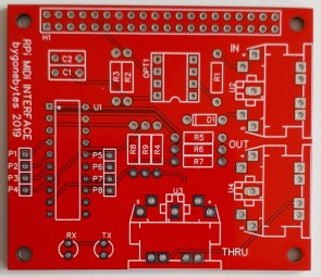
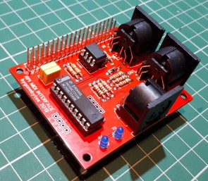
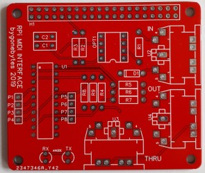
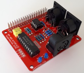
The first step was to test the interface on the bench, just as well as I had miss read the data sheet for the 74HCT245 and got the buffer direction wrong. Easily sorted with a couple cut tracks and wire straps on the underside of the board. I have updated the board and ordered replacements, just to make them different the new boards will have rounded corners..
I have set up a Raspberry Pi3 with Raspbian Buster then modified the raspberry Pi's serial port as per the instructions on AB Electronics web site to enable the Pi's serial port. I could test this with my data simulators as they were written to work over an RS232 interface - same port on the Raspberry Pi.. The simulators work at 2400 baud so transmitted data changes can be easily seen on the Tx LED, I up'ed the baud rate to 31250, the MIDI baud rate, and the faster transmissions can be seen on the LED as the burst of data is much shorter.
I wrote a quick and simple program to assist with the calibration of the Midimuso CV-12 providing buttons to transmit MIDI 'note on' (pitch) codes for 1V steps from 0V to 10V and MIDI 'note off' to test the gate output. The screen is shown below.

Connecting the CV-12 to the Raspberry Pi through the 5 pin DIN MIDI cable was simple and the messages from the Raspberry Pi were received without any issues. This was a lot simpler than I thought given the amount of issues I've read about on the internet. Below is a photo of my test setup, I now need to assemble the CV-12 onto a module front and then think about what funtionality I want from this controller.. Touch screen, inputs - pressure sensitive..etc.
To download the example program and Gerber files to make your own boards (Easy EDA - $2 plus postage for 5 PCB's) visit the Raspberry Pi MIDI page.
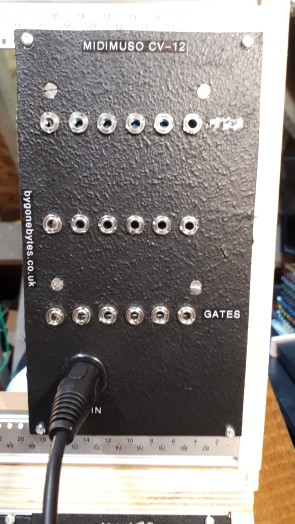
The Midimuso built into a module and mounted in the rack. I've still to try the different modes and will do this once I have more envelopes/VCA's ready.
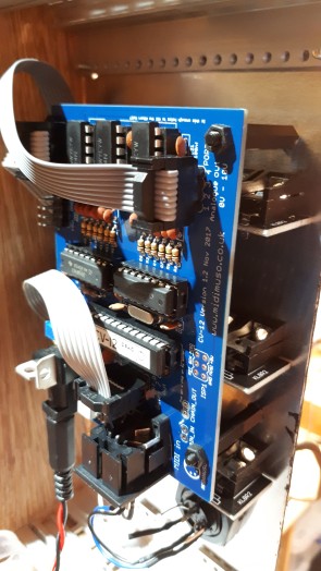
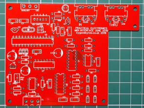
The PE MIDI interface is part of a full monophonic synthesiser so when the kit arrives it does not come with a separate circuit board so I designed a board to fit both my Modular Synthesiser and the Maplin 5600 Synthesiser.
LFO - Low Frequency Oscillator
Sample and Hold
The build so far..
