A very worth while addon for the Electron is the MRB which adds Shadow Memory and a Turbo mode which almost trebles its speed. The Electron page mentions that I had the original Slogger Master RAM Board and has links to the fitting instructions, well now I can show photos of the installation courtesy of a newer version which is currently available (2021).
The MRB kit is delivered with all the components needed in an antistatic bag, the bag contains the following:
The Board itself populated with all components except the 6502.
Links and shunts
Optional extras are the 6502 and low profile 40 pin IC socket.
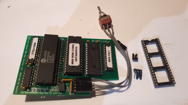
Whilst the MRB layout has changed the method of installation is the same. The board fits all issues of Electrons with minor variations due board layout differences. This photo guide follows the installation of a MRB into an Issue 6 Electron. Tools required are:
A good Soldering Iron with a fine tip.
Solder.
Small flat blade screwdriver.
No3 Cross point screwdriver.
Small cutters (snips).
Craft Knife
Tweezers.
Solder Sucker and de-solder braid.
IPA to clean board after desoldering.
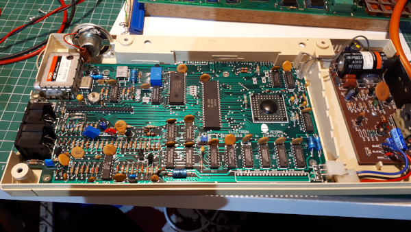
An Issue 6 Electron opened ready to start.
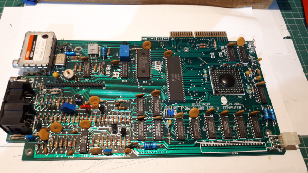
Removing the Motherboard - Remove the DC and AC power connectors and the speaker connector then remove the 4 screws that secure it to the case.
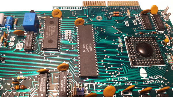
Identify the 6502 Processor and Link 13 (Issue 6 board only).
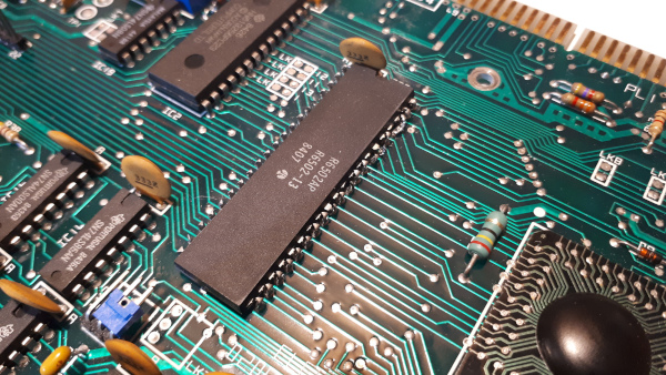
The easiest way to remove the processor without damage to the PCB is to cut the legs from the processor (Only do this if you have a replacement 6502!).
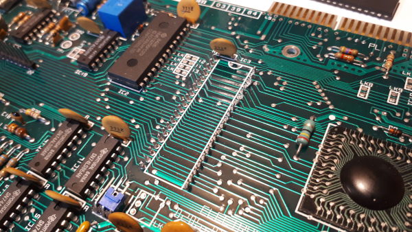
Remove the processor body.
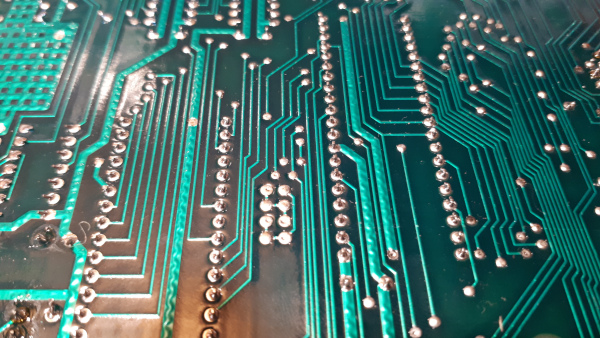
Identify LK13 on the under side of the PCB.
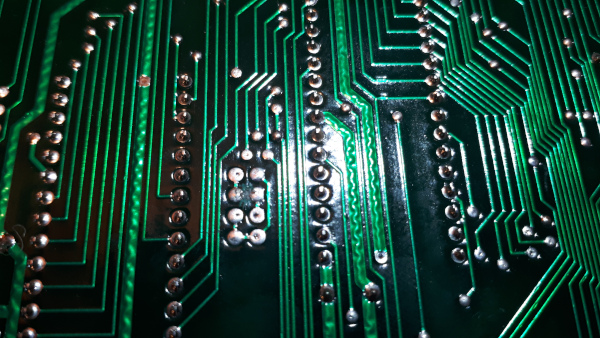
Cut the track between the left and right pads.
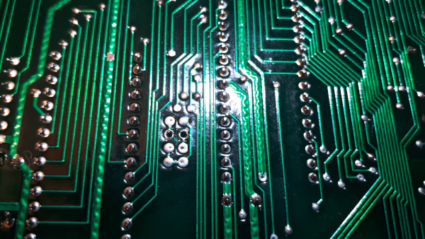
Use a solder sucker to remove the excess solder to reveal the holes.
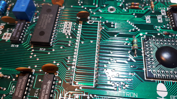
Start removing the remains of the processor legs using the soldering iron to melt the solder and tweezers to gently pluck them out.
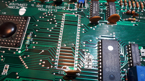
Continue until they're all removed.
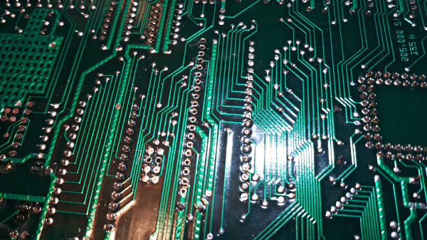
Use the solder sucker to remove the excess solder.
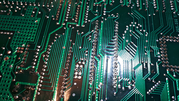
Continue until they are all clean.
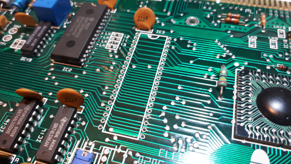
Clean around the holes on both sides with IPA.
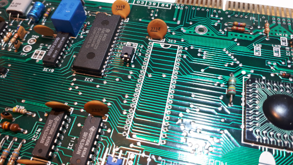
Fit the link to LK13 and solder.
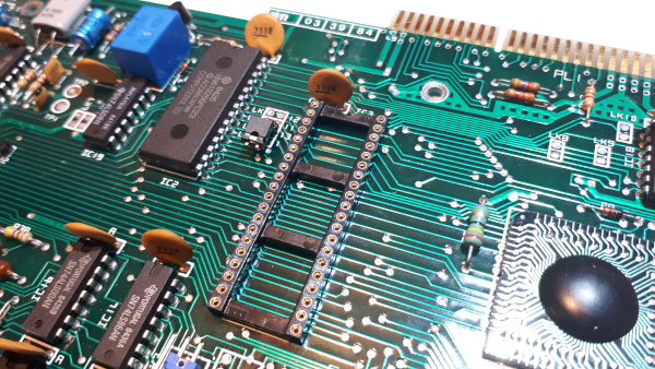
Place the 40 Pin Socket into its position - ensure the correct orientation.
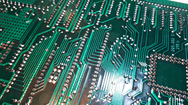
Turn over the PCB.
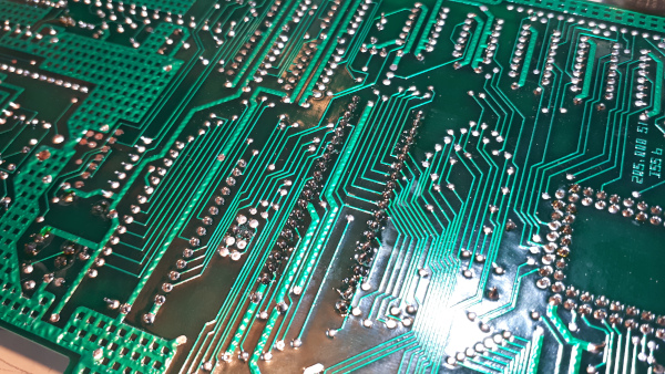
And solder.
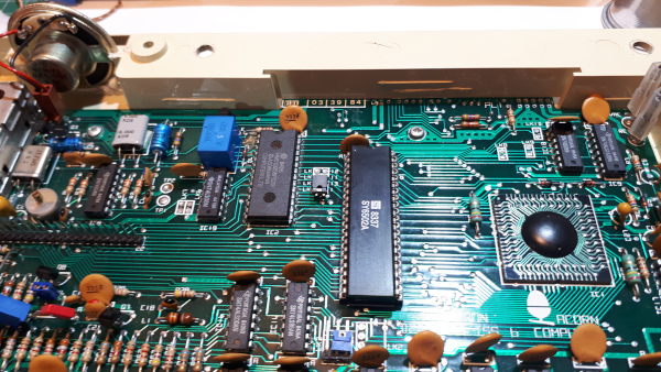
Turn the PCB back over and insert the replacement 6502 processor then reassemble the Electron to test that the work done so far is correct.
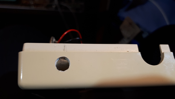
Now drill the case with a 6mm drill for the mode selection switch.
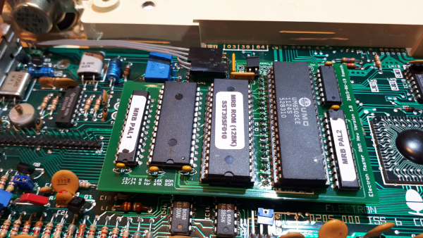
Remove the shunt from LK13 and plug in the 2 pin flying lead in its place. Ensure it is in the correct way round.
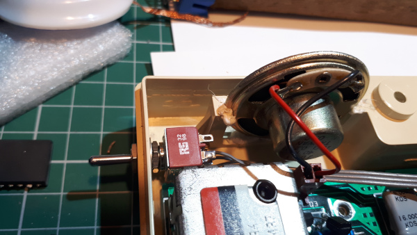
Fit the mode selection switch.
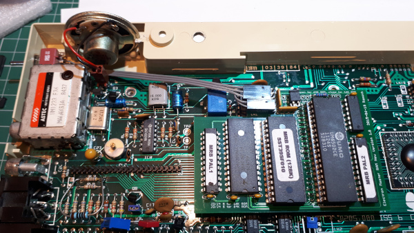
Before fitting the MRB four disc capacitors need to be gently bent over so they don't foul the board when fitted - Align the 40 pins on the MRB to the 40 pin socket and press firmly into place.
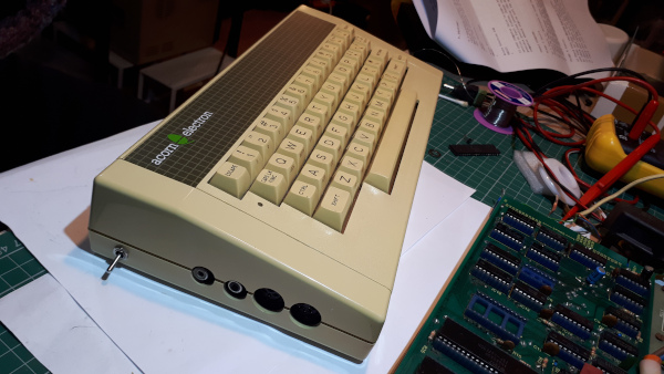
Re-assemble the Electron for testing.
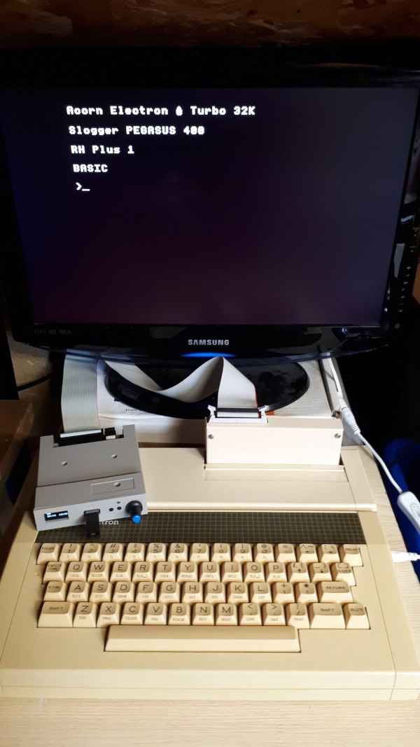
Testing the Turbo Mode.
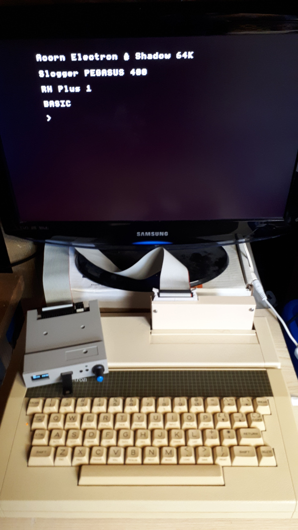
And testing the Shadow Mode.
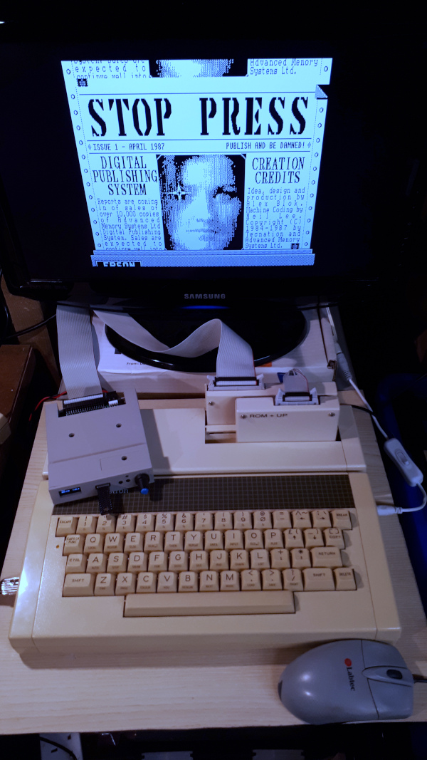
And finally running Stop Press in Turbo Mode..nice and fast..
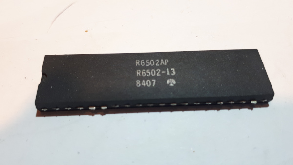
Now should I try soldering wires on to the legs of the 6502 so I can use it for testing..