Aviemore Train Describer - 1980
The Signalling Electronics Section started designing and building its first Train Describers in 1980 with the Aviemore installation. Aviemore Train Describer is more a Train Reminder than a Describer as it used a single character display. At its heart was a Intel 8080 processor development board, SDK80, mounted in a horizontal card frame and connected to a 6U card frame housing several types of our 6U and 3U cards, each type performing different functions of the TD. The cards type were:In the signal box the signaller would have his keyboard and on the panel 16 single character displays. In the back of the panel there was power and data distribution for both the keyboard and displays.
I produced the artworks for the keyboard and displays then photo etched and drilled the boards - I made about 25 displays and 2 keyboards. The display cases were made at the S&T workshops in Irvine and were designed to fit the double skined panel, nylon front with steel matrix on the back. The display simply fitted by inserting the top flange between the two layers and its weight kept it in place. The keyboard consisted of dedicated keys for each berth and descriptions - that took a bit of drilling, painting and wiring..37 keys and each needed its key cap legend rubbed on with Letraset lettering.
I have a limited amount of constructional details left, mainly around the areas I worked on and very few photos. I searched the internet and found two pictures of the panel, one at each end of it's life.
Below are the details I can find:


The Micro Processor board at the heart of the TD.


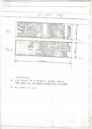

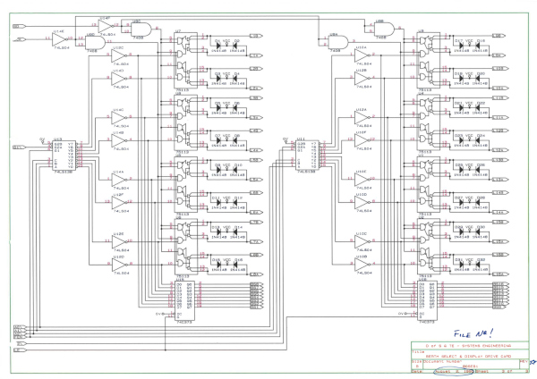

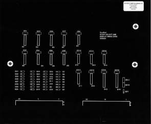
Artworks for the Clock & Display Converter and Berth Select & Display Drive cards.
Software development for the SDK80 ScR TD's
To write the software for the Intel 8080 development board (SDK80) we bought the MDS800, universal EPROM programmer and In Circuit Emulator (ICE). To input and print the data we used TI Silent 700 thermal printer - you can just see it sitting on top of our MDS800. The Universal EPROM programmer had two personality modules, one for the 2708 (1K) and the other for the 2716 (2K) EPROMS. The MDS800 was used for two SDK80 based TD's, Aviemore and Hyndland, basically until the SDK80 board was discontinued.The first photo is our MDS800 in the office (beside the BBC Computer!) and the others are taken from the internet to show a bit more detail.


Hyndland Panel Extension Train Describer - 1981
Hyndland's area of control was being extended to cover the Finneston area with an extension to the existing panel with a new Henry Williams 'Domino' panel. The existing Train Describer was an old STC relay system which would have been difficult to extend so with the experience of having built Aviemore TD we used the same Intel 8080 microprocessor development kit and display drive cards to run the system. The displays used were Westinghouse four character dot matrix displays as used in the Edinburgh TD fringe box units.We designed two new 6U TD I/O interface cards to pass TD desriptions between the STC Relay TD and the new micro processor extension, all hand wired!


Hyndland TD Modules.


Auxiliary I/O Card & 50V Interface Card.
High Street Train Describer - 1983
 High St. was our first fully fledged Train Describer, new cards were developed, some taken from the earlier Aviemore TD and others designed from scratch.
The processor card used was a Mostek Z80 on an extended (220mm deep) 6U eurocard, this caused some problems with the build as all the other cards were standard size (160mm). To keep the cards in line at the front the backplane was split level making it difficult to wire tidily.
The Berth Stepping card was completely redesigned and the Master Routing card grew from the Clock and Display Converter card. By this time microcontrollers had got a grip and we designed them into virtually every new card. Thus the four character display was updated, gone are the EPROMs being replaced by an 8748 micro controller. This simplified the hardware, making the cards smaller with a new case being designed and manufactured to be a direct replacement for the tube displays used in the major signal boxes in Scotland (again looking ahead!). Of course High St. didn't have this style of panel so additional metal work was required to hold them in place.
Other cards benefiting from the microcontroller revolution were the keyboard and the Auxilliary I/O card. The keyboard was our first full alphanumeric board with interpose/cancel/interrogate/reset function buttons and alarms. The Auxiliary I/O cards were a means to get miscellaneous bits into and out of the TD. .
The core TD cards were professionally tracked and manufactured, the interface and keyboard cards were manufactured in-house using photo etching and a bubble etch tank.
There are not many photos of High St TD exist but I did manage to find this one however what I do have are the full circuit board designs and photos of the High St. TD Display Modules.

Mostek Z80 Single Board Computer (OEM-80) with the DDT-80 OS.


Berth Select & Display Drive and Berth Stepping Card.


Master Routing Card & Display Module.


Tx/Rx Card & OCU Card.


The third design of the Display Module! It was designed to fit a Henry Williams 'Domino' tile panel as at this time the three major signal boxes in Scotland, Glasgow, Motherwell and Edinburgh all used HV tube displays so we thought our case should be a physical plug in replacement. Funny thing is it was never fitted to that type of panel.
Dundee Train Describer & ATR - 1985
 Dundee TD is a 31 berth/128 step describer which built more functionality in to our system by adding Fringe Box Units, an ATR Co-Processor and what we christened a MULDEM.
 The MULDEM used the DAM Multiplexing and De-Multiplexing cards to bring signalling information directly into the TD for Early Transmission (ET) and to send Berth Occupied out for use as conditions in the stepping meshing.
Dundee Automatic Train Reporting (ATR) was installed during the TD works with only the local ATR printer installed on the operating floor.
It was the intention to add a further six printers around the station area and one in Glasgow Control but this never came to fruition, although all the hardware was purchased the Telecoms lines were never made available and the project was quietly forgotten.
The Train Describer was finally decommissioned on the 26th September 2021 - 36 years is an exceptional operational lifetime for an electronic system. .


Dundee ATR & TD Cubicles. A Dundee TD Module.


The TD Display Distribution, keyboard and auxiliary cards - New and 30 years of dust.


Dundee TD Display Distribution inside, Display Connectors and with 30 years of dust.


Dundee Fringe Box Units under contruction in 1985 and the Panel Keyboard after 30 years of use.
Dundee TD Fringe Boxes


Broughty Ferry SB was one of the original Fringe Boxes of Dundee until it closed in March 1995. The fringe is now Carnoustie SB.


Carnoustie SB is the new Fringe since 1995. This isn't the orgininal FB Unit as the new one is grey in colour.


Longforgan SB with TD Fringe Describer.


Taybrige South SB with TD Fringe Describer.
The full design is documented in the Site Manuals, volumes 1 & 2 but how we went about the design may have been a bit unusual. This is before CAD! We used a Cut & Paste system - by drawing out a DIN41612 edge connector, copying and pasting on a large sheet of paper and pining it to the nearest convient wall we drew the backplane wiring between edge connector pins. The original Upper and Lower backplanes designs:
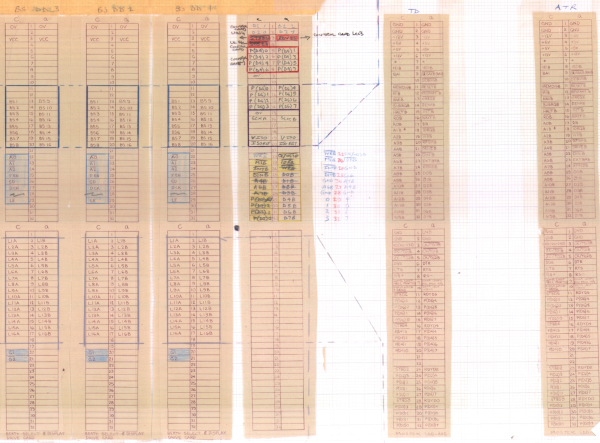
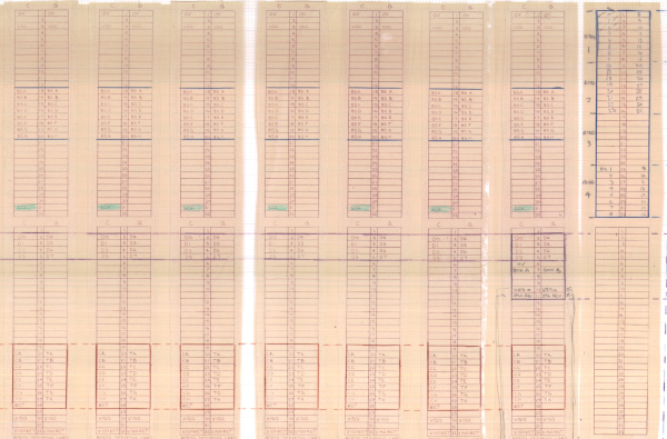
The upper and lower card frame edge connector design.
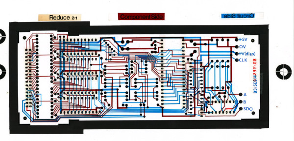
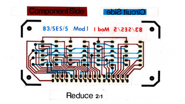
All the circuit board and faceplate designs were first hand drawn then sent out to PCB design company, ACD Ltd, Linlithgow, for the RED/BLUE tape layouts to be made. As an example the TD Display unit:
The original manual was written in Interword & Technocad on the BBC Micro Computer and later (1992) converted to an MS Word 2 & Microstation document with the final update being in 1995 with the closure of Broughty Ferry SB.
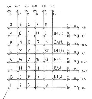
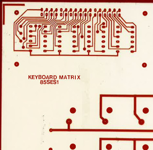
Early Train Describers used ABC keyboards which we built using an ASAD card and a keyboard matrix. The keyboard matrix also had three display fronts for BERTH, DESCRIPTION and ALARMS. Above photo of the Dundee keyboard.
Cathcart Train Describer - 1986
 Cathcart TD was a 64 berth/80 step describer with capacity of adding a further 80 steps which is over twice the capacity of Dundee. It also added more functionallity such as box-to-box links
and a Buffer System to send TD data to SMA (or TTR or DOO) and LLPA.
Cathcart TD was a 64 berth/80 step describer with capacity of adding a further 80 steps which is over twice the capacity of Dundee. It also added more functionallity such as box-to-box links
and a Buffer System to send TD data to SMA (or TTR or DOO) and LLPA.The box-to-box links require a mention as both links (actually 3 links, two to Glasgow Central over one physical link and one to Motherwell) communicate with GEC-Elliot 905 computer based TD's. These TD's required an additional ScR system added to their Automatic Peripheral Cpntroller (APC) to facilitate the communications. This will be covered on a separate page.
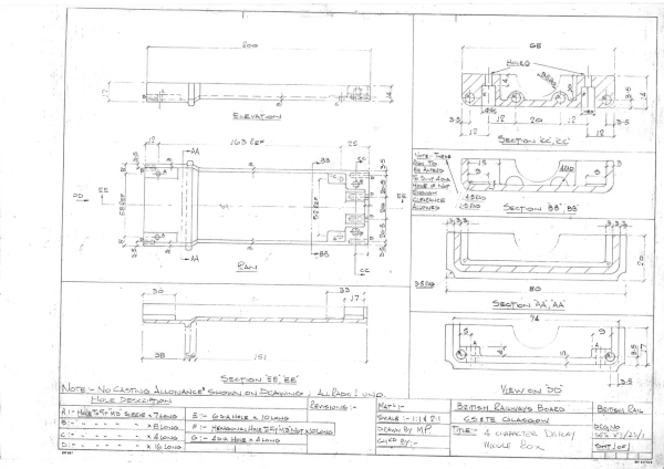
The Cathcart Train Describer displays were a bit different than usual as they were elecro-mechanical with reduced height characters and Track & Route indications built in on either or both sides of the TD display. For the LED replacement display we had to provide the same fuctionality and fitting arrangements so we designed a new case with the same front dimensions but extended to accept the same display circuit board we designed for High St. but with a new dot matrix LED front panel and Track & Route LED's.
The original Track and Route indications used light pipes to guide either red or white (Yellow) light to a single indication. In 1985/86 there was no such thing as a white LED or in fact a bi-colour LED of the small size required so we contracted an LED supplier to pot two LED's, a Yellow and a Red into one package.
The TD was replaced in 2007.
The photographs I have for Cathcart TD are all a bit out of focus so I've selected the best of them to show the different aspects of the system.
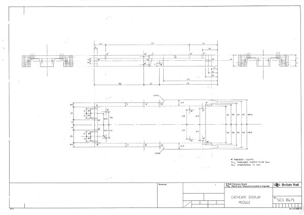
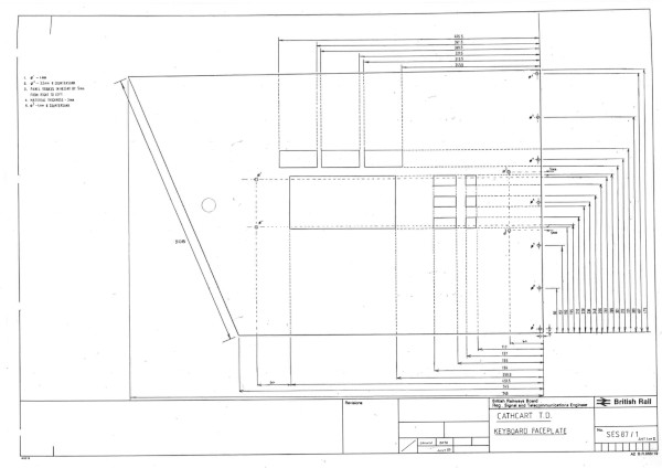
Two other parts of the design, the TD Display module and the keyboard, both modeled on the original items.


Cathcart TD Cubicle.

Close up of the upper 6U rack which was populated with Master Routing Cards, Berth Select & Display Drive Cards and Control Cards.


Cathcart TD Mostek Z80 Single Board Computer (OEM-80) with the DDT-80 OS and Keyboard with the three setup berth displays.


Cathcart TD Display, old and new.
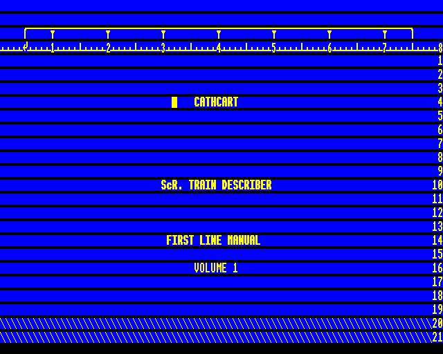
The TD manual was written using Interword on a BBC Computer and was transferred as text files for later conversion to a PDF file but his never happened so I have included both the Interword and text files.
The document is written in sections to accomodate the memory limitations of the BBC and once printed it was compiled into the final document.
At the time Interword was a better 'what you see is what you get' word processor compared to Wordstar or Multimate which formated text in a similar to AcornSoft View - you don't see the page formatting until it's printed.
Greenhill Train Describer - 1990
Greehill Train Describer was a 64 berth/80 step describer with the backplane wired as a 64 berth/128 steps and once again added more features such as a VDU display instead of the traditional four character display modules and links to TRUST.There were two box-to-box links and two fringe-box links at Greenhill, The Greenhill/Polmont link is a box-to-box link, although the link was in fact between Greenhill and Edinburgh as Polmont is a Satellite Fringe Box of Edinburgh TD and hence the data was passed through Edinburgh TD to Polmont. The other box-to-box link was to Cadder TD.
The two fringe-boxes links were to Cumbernauld and Carmuirs West where we install our standard ScR fringe-box units.
The TD console consisted of a pedestal topped with a desk unit, both manufactured by Rittal. The 20" colour monitor, supplied by Terminal Display Systems (TDS), was mounted on the desk unit top plate, and the ScR keyboard matrix on the desk unit hinged panel. The monitor had a swivel base, allowing it to be angled to suit the convenience of the signalman and the TDS Super Colour 6000 graphics computer system, which drives the monitor, was mounted within the desk unit.
The TD cabinet situated in the RR was a 39U high VERO case which contained the 3U power supplies rack, the 3U modems rack, the 6U card frame carrying the TD computer, the cards constituting the ROUTEING SYSTEM and INTERFACE BUS, and the ET satellite, the 6U card frame carrying the cards for the STEPPING BUS, a 6U card frame carrying spares and a 700VA uninterruptable power supply.
The Backplanes for each 19" rack was drawn on a long scroll and is the 'master' record of the design. This was transposed on to the rack using wire wrap.

Being the newest ScR TD I would have expected to have more details than I have, very few photographs have survived just the Fringe Box Units when they were being built in our office. The Maintenance manuals have survived and possibly the Novcad Drawing files.
Two new cards were made which were an RS232 to 422 convertor for all the serial links between the Panel and the RR and one used for monitoring the lineside of four wire modem links. It was used in conjunction with our Feline line monitor.


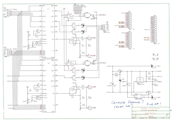
The Dual RS232-422 converter and th Modem Monitor.
As with other TD manuals this one was also written using Interword on a BBC Computer and was transferred as text files for later conversion to PDF format but this did not happen so I have included both the Interword and text files.
The document is written in sections to accomodate the memory limitations of the BBC and once printed it was compiled into the final document.
During 2021 I spend some time refurbishing some TD display modules to make this short video: