Cathcart / Neilston DAM - 1982
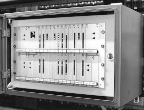 Cathcart/Neilston - 28 Controls, 42 Indications
Another opportunity came our way this year, the Cathcart / Neilston project required a cheap TDM system to send and receive controls and indication data between the two sites.
The concept of the architecture design was worked by other members of the team with the card designs following shortly after, my job was how to implement the hardware.
The final design would have some novel concepts that up until then had not been seen on a TDM before.
Firstly it would be compact, asynchronous, respond to changing inputs immediately (Change of State) and have bit indication LED's on the input and output cards for easy faulting.
Three cards were designed, a processor card (control card), an 14 bit input card (Multiplexing card) and an 14 bit output card (de-multiplexing card). The processor card would be programmed for both input and output function with selection achieved by a backplane link.
The hardware was designed around the KM6 6U sub-rack with a 3U sub-divide for power supplies and modem. The power supplies were encapsulated 110V to 5V and +/-12V mounted on 3U cards with indirect edge connectors and the 3U modem, 1200 baud full duplex, was sourced from ITT in Sweden.
During the contruction of Craigendoran DAM a flaw was uncovered with the ribbon DIN41612 connectors so the cable was subsequently changed to a PCB backplane.
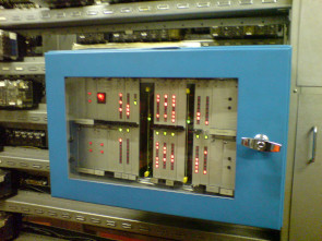
The final implementation was two 6U high wall/rack mounting cubicles as can be seen above - very small compared to other manufactures of the time, one or more 19" cubicles!!
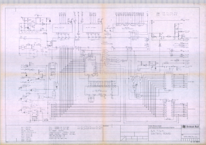
The full hardware design is available here along with our first attempt at a Technical Description and Maintenance manual, something we had sadly neglected in the past, future manuals get very large.
Cathcart DAM Extension to Kirkhill
Cathcart/Neilston 14 Controls, 42 IndicationsCathcart/Kirkhill - 14 Controls, 28 Indications
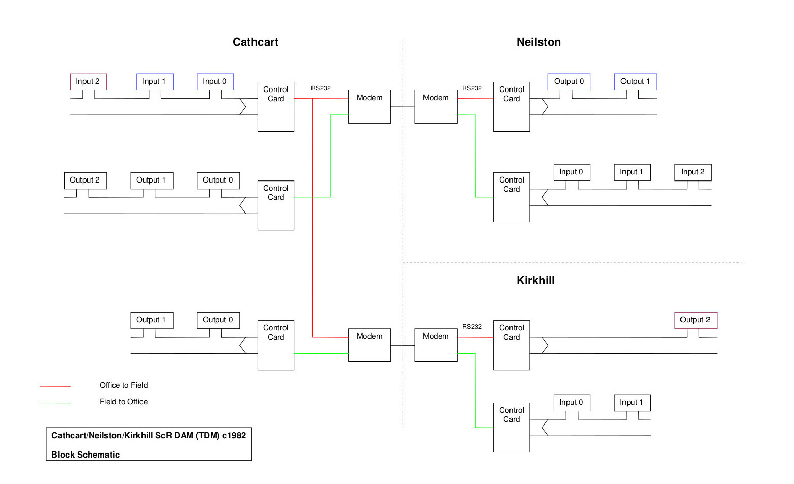
Sometime later the Carthcart DAM (TDM) was extended to add Control and Indication functions to Kirkhill. There was very little space in the cubicle so it was decided to extend the DAM in novel way, part multi-drop. The Block Schematic describes the final achitecture of the system.
The office end Input cards are scanned by the Cathcart Control card with the serial data being send to both Kirkhill and Newton. The relavant output card at each field end was hardwired with their identity so only the data for that card can be output.
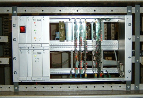
Kirkhill, one of the Cathcart DAM Field ends.
Block Schematic
The Software
The Control Cards employ an 8748 micro controller with 1K of on board EPROM, this was programmed with both Tx and Rx routines which are selected on power up by reading a hardwire identity on the backplane.The Input Control Card scans each card in turn and sends the input states along with their addresses to the field end Control Card to be output. The Input Cards have hardware that detects if an input has changed and interupts the Control Card scan and send it imediately to the outout so a near instant response is given.
Conventional TDMs worked on time cycles and if an input just missed it's time on a cycle it would have to wait until the next cycle before it is sent. This could lead to a maximum delay of 2.5 second. The DAM System was very resonsive for the Signaller, just a tap on a button instead of press and hold!
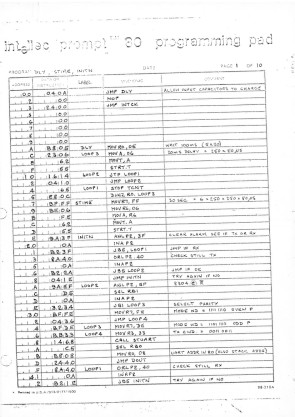
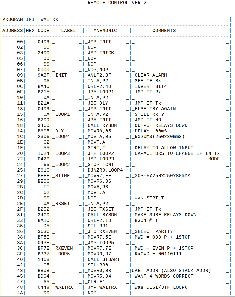
The original hand written program and version 2
Craigendoran DAM 1984
Craigendoran 84 Controls, 280 Indications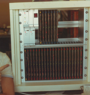 The Craigendoran DAM system was used to pass Control and Indication data between the Control Panel and the Relay Room below. This architecture was implemented with the
recontrol of Craigendoran from Yoker IECC in mind - Simply move the Office end TDM to Yoker.
The Craigendoran DAM system was used to pass Control and Indication data between the Control Panel and the Relay Room below. This architecture was implemented with the
recontrol of Craigendoran from Yoker IECC in mind - Simply move the Office end TDM to Yoker.Craigendoran TDM uses the same cards as the earlier Cathcart TDM but with a different construction. The Office unit was built into Vero X Frame 12U cubicle with the I/O connector blocks in the rear. The Field end was mounted on a Rack in the Relay Room with covers on the back to prevent accidental touching.
Some improvements were made to the physical layout of the cards, no front aluminium panel, better LED indications and the cards silk screened. This was a big system, 84 controls and 280 indications with each end useing two 6U 19" racks. The power supplies are now BICC Vero PK55 and PK60's and the modem remained ITT 1200 baud.
Some problems were encountered with the construction of the upper back plane. Cathcart was built using 64 way ribbon cable pressed onto DIN41612 edge connectors. This technique was initially employed on the Craigendoran build but it quickly became apparent that there was a flaw with this - the back of the edge connector bolts to the card frame and every time a card is removed it pulls the front of the connector away from the ribbon cable causing intermittent connections to the ribbon cable. Changing the ribbon cable to a bussed PCB with soldered DIN41612 connectors not only solved this but made the construction quicker and simpler. Cathcart was retrofitted to maintain reliability.
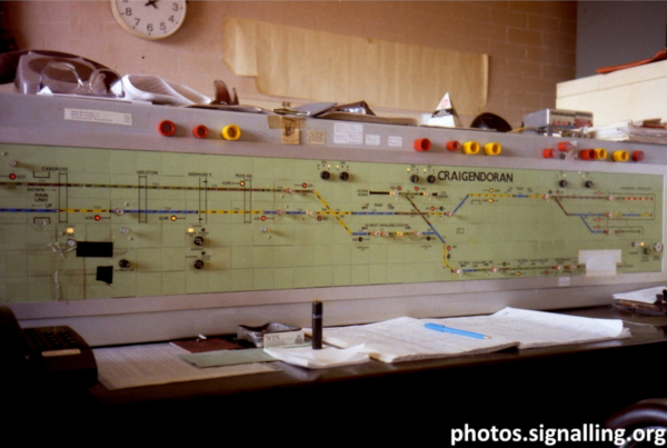 Craigendoran Panel where you can just see the cream coloured DAM cubicle on the right.
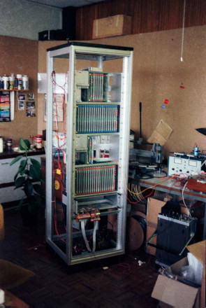
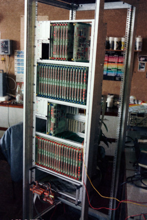
Craigendoran DAM under contruction and testing in the office.
Craigendoran DAM / Yoker - 1992
Craigendoran / Yoker - 84 Controls, 322 IndicationsCraigendorn re-control finally came on 1992 but is wasn't as simple as were thinking in 1984. The IECC would interface with the Field end DAM through an RRI with dual diverse routed telecoms lines and the Control Panel was to remain as an emergency panal. This setup meant we had to come up with a solution to upgrade the DAM with dual auto line change-over and the ability to route them to the Office end DAM for emergency working.
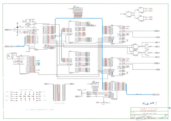
As part of this upgrade we also increased the quantity of Indication bits to 322, this lead to utilising the spare space in the Control rack for the extra Multiplexing Cards. Two new cards, a Line Routing Card and a Bus Bender card were developed for the upgrade along with using our own Modem design from 1989 - The ITT modems were getting difficult to get so we developed our own to reduce reliance on other supplier.
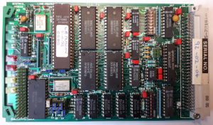
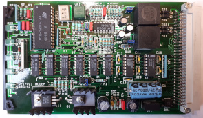
With a new Line Routing Rack required we decided to move the whole Field end DAM into a 19" cubicle. This of course was a challenge, shutting down the DAM, uncoupling all internal/external connections, unbolting the frames from the rack reinstating it in the cubicle, reconnecting everything and testing it in one 12 hour shift but we did it!
As you'll see our manuals have come a long way since Cathcart, this one incorporates all the changes for the Yoker upgrade. Our manuals were written using Computer Concepts Interword on a BBC B+ computer and printed on a Epson LQ1000 letter quality dot matrix printer fitted with a cut sheet feeder. The CAD drawing were produced on Technocad also on the BBC Computer.
During the 1984 build I developed a Spreadsheet on Intersheet that contained a complete materials list including suppliers part number and prices. To create a materials list and costs for any future DAM all you had to do is enter the number of Controls and Indications.
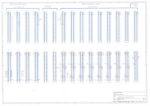
The Craigendoran/Yoker DAM backplane wiring.
Glasgow Central to Cardonald DAM - 1988
Glasgow Central / Cardonald - 42 Controls, 70 Indications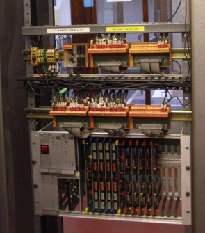 The Cardonald system was built around the now well tried and tested design that was used in Cathcart and Craigendoran. As there was very little space in Glasgow Central RR it was decided that
the DAM would be built into an unused type D remote control cubicle.
The Cardonald system was built around the now well tried and tested design that was used in Cathcart and Craigendoran. As there was very little space in Glasgow Central RR it was decided that
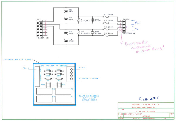
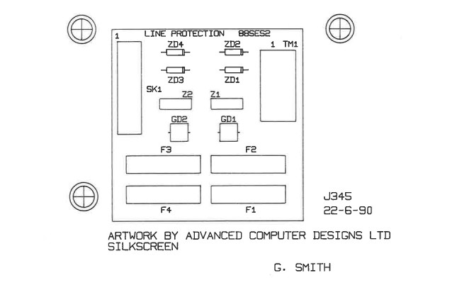
the DAM would be built into an unused type D remote control cubicle.The only technical difference was the use of additional lighting protection. Instead of relying on the Telecoms line protection a new card was designed to give extra and faster acting protection.
The card consisted of a set of fuses, a Gas Discharge tube and a Zenamic voltage dependent resistor and can be seen to the left of the two orange Klippon Blocks.
I remember that on one occasion I visited Cardonald RR I found that the roof was leaking and rain water had been dripping down through the DAM card frame. One of the Control Cards had severe water damage, a large wide strip of brown gunge ran the full length of the board but it was still working! The leak was fixed and the card was replaced.
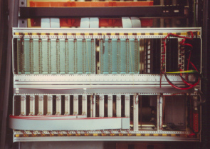
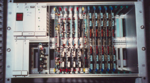
Cardonald DAM Office end.
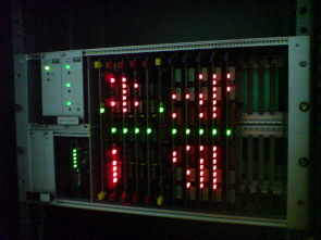
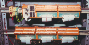 Cardonald DAM Field end.
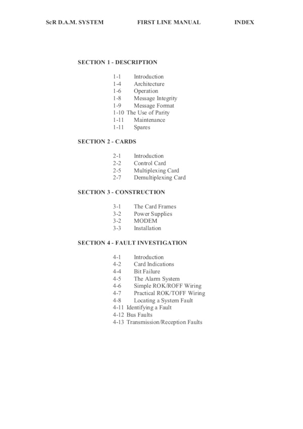
The Manual was written using Computer Concepts Interword on a BBC B+ and eventually converted to PDF. The ZIP file contains the original Interword files and the Intersheet file, DAMCOST, which was used to estimate the hardware costs. Entering the number of Controls and Indications in the relevant fields it not only calculates the total cost including spares but also a full Bill of Materials.
Note: The file is in .dsd format for use on a BBC Emulator or BBC computer with Gotek drive with Interword & Intersheet.
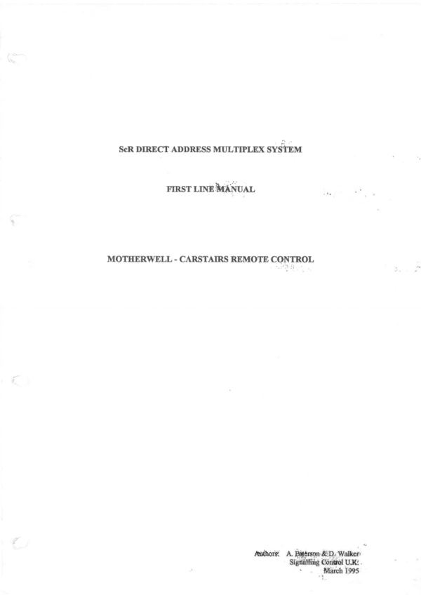
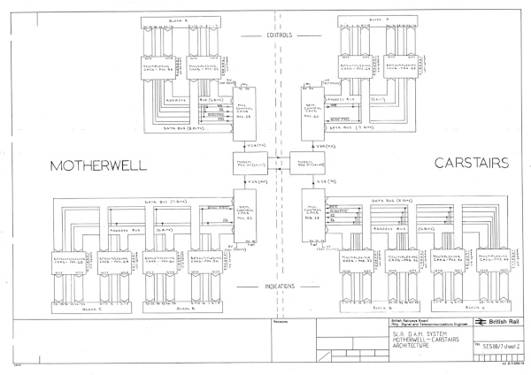
Motherwell to Carstairs DAM - 1988
Motherwell / Carstairs - 28 Controls, 56 IndicationsThe Carstairs system was built at the same time as Cardonald and was very similar in construction.
Glasgow Central to Shields DAM - 1992
Glasgow Central / Shields - 84 Controls, 168 IndicationsShields DAM was our last TDM to be built and it benefited from the newly designed Automatic Line Change Over rack developed for Craigendoran. Adding dual telecomes lines improved system availability and thus reliability.
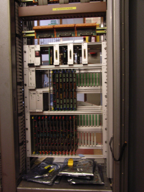
Shields Office End DAM.
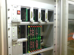
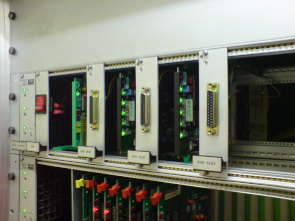
Shields Field End DAM with Line Change Over Rack and Line Routing Card Design.
Other Remote Control Systems - from 1985 ish
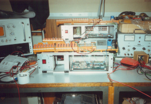
When the ASAD Micro Controller boards was developed it was ideally placed to be a small remote control system.
A 16 bit system could be built with just one card, modem and PSU, so this one was built for use as a standby system for St. Germains CCTV but was not required in the end.
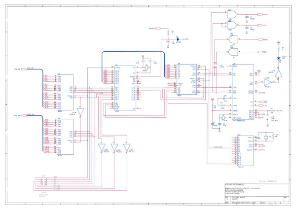
By 1994 we put what we had learned from the ASAD and Modem cards to bring together a single Eurocard TDM that sported 16 bits of fully buffered I/O with built in 2/4 wire 300/1200 baud modem.
The design was never completed but you can see we were always looking for ways reduce the size and cost of these systems.
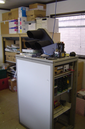
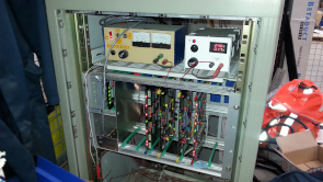
And one last DAM system and probably the longest running one of them all, the test rack. It consists of a rack with space for two Multiplexing & De-Multiplexing cards, and a modem with its lines looped back. It was built into an old cubicle with a switch box to simulate inputs and an old ground signal to load the outs.