PC Controlled 64 Way Switch Box - 2008
Over the years one of the most used pieces of test equipment is switch and lamp boxes. These are used during Factory and Site testing of TDM and PMUX equipment. We found that there were some limitations to basic switch boxes such as there is no record (log) of the testing except for tick marks on testing sheets so we set about building PC Controlled switch boxes.In 2008 the Babcock Rail System team looked at how to go about automating and logging the testing, ideally the boxes would be controlled via USB, have 64 switches and have LED indications. The software would have the facilities to control two switch boxes, switch each switch individually, have preset patterns, predefine switch names and log all switch and control changes.
The first decision was to select a USB controller and output drivers and we settled on the Maxi-Bee and Beedriver boards from PC-Control. The free software available, Bee-Step64, was a good starting point but we found it didn't have the facilites we wanted so we set about writing our own. Below is a photo essay of the Switch Box build, testing with beta 0.2 software and screens from the final version, v1.0.


Laying out the major parts for fitting the console case and working out the vero board layout for 64 relays.


Drilling out the holes for the power & USB connectors and the mounting holes for the PCB's and power supply.


Drilling the holes and mounting the 37 way 'D' type ouput connectors.


Wiring the relay board.


More wiring.


Wiring to the Beedriver boards.


Drilling more holes and mounting the LED's. Building the second switch box.


Connecting the driver boards to the Maxi-Bee and wiring the internal power and USB.


Finishing th wiring and making it tidy.


Wiring the second switch box. We left off the LED's on this box!


Using the beta 0.2 software for testing.


Testing continues.


Hardware testing complete.
Writing the Software
The software was written in stages slowly building up the fuctionality. Initially just switching the first 64 relays with the click of a mouse then adding on the second box. Further facilities were added such as giving each button a function name, save & loading the button names, printing the names list, saving, loading and printing the log window.


Initial program screen and the first screen to incorporate two switch boxes.


Starting to add the button functionality.


Adding more fuctionality, right clicking a button allows editing the function name.


Preset functions such as 'All On' and 'Even On'.


Functionality complete.
The software was written in Visual Basic using .Net v2 and run on Window 2000. The latter screenshots were taken in Window 10 explaining the look change. Version 1.0 has the button function names 'greyed out', I'm not sure if this was deliberate or an incompatibilty through using Windows 10. The names can still be edited by saving the 'Nomenclature' and editing the text file created then load it back in - it's actually much quicker to edit this way and harder to accidentally change so it may have been a deliberate decision.
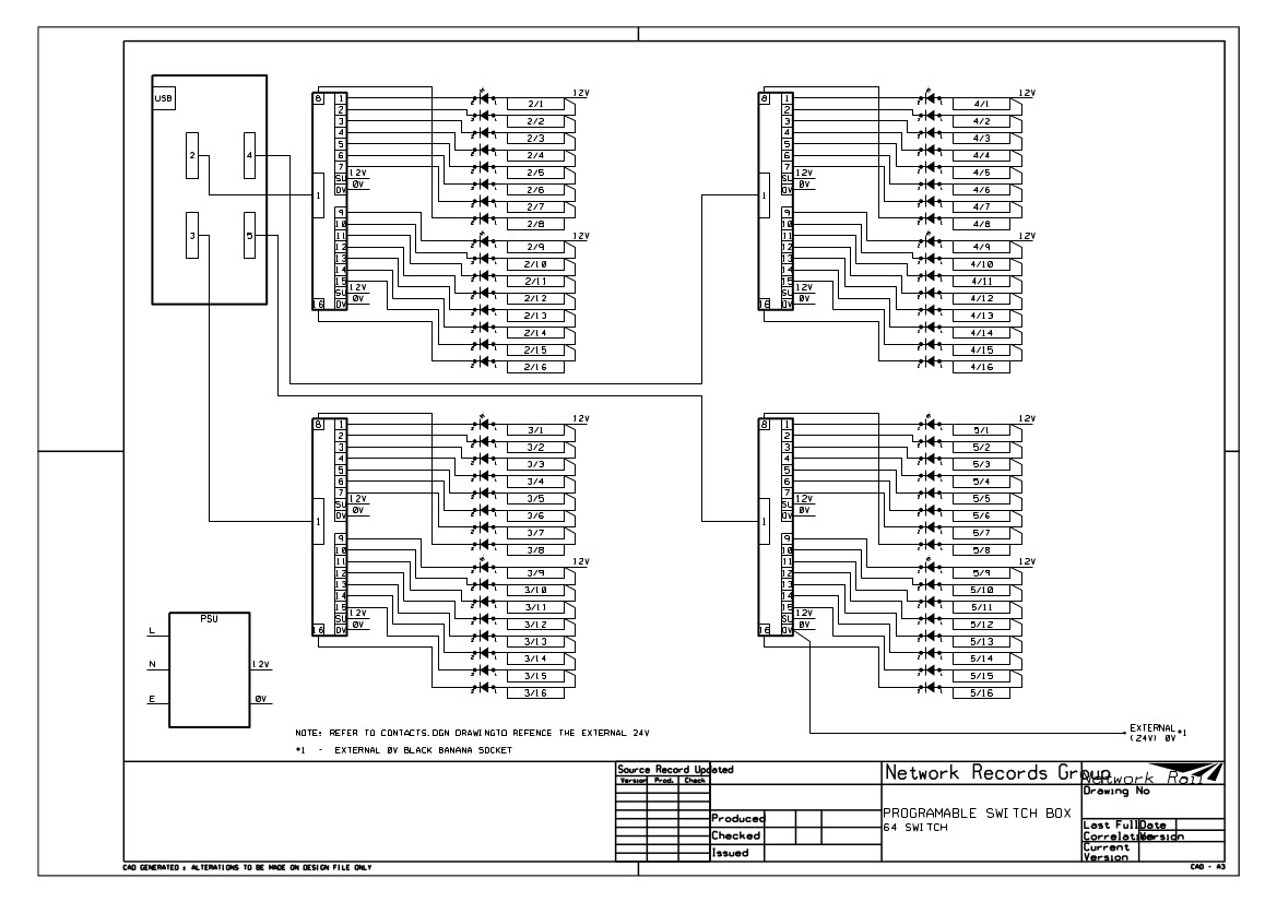
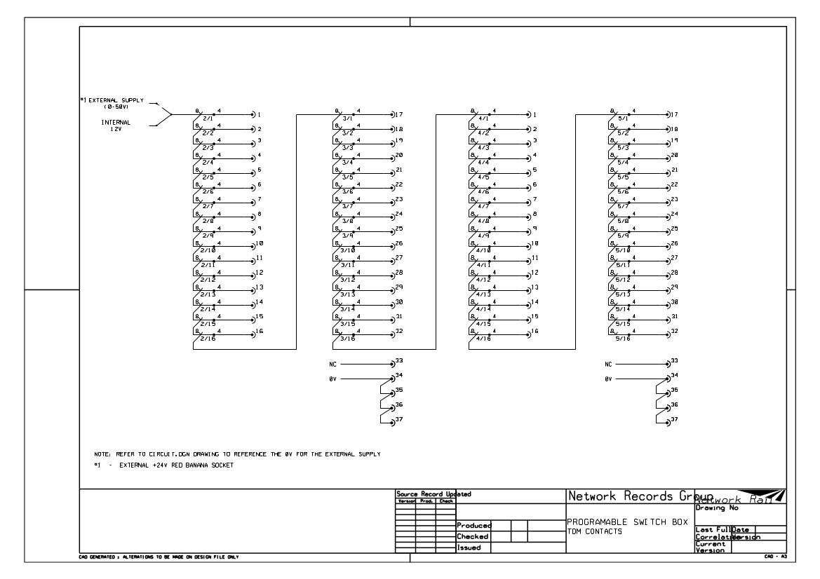
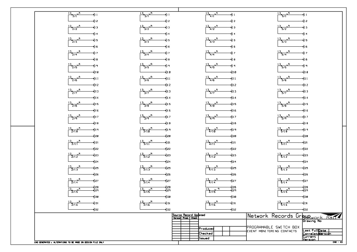
Wiring diagram
There are three drawings, the circuit or block diagram and two for wiring relay contacts for Event Monitoring and TDM inputs. The four 37 way 'D' type connectors on the rear of the case are split two for TD/TDM and two for Event Monitoring.
The program
The executable and the dll files.