85SES3 Display Module Tester v3
 Following on from the Train Describer Display Module Clock project I thought I'd resurrect another old piece of kit from around 1985, the TD display module tester. I thought it would be a good idea if I
get could at least one example of display module from each version of our Train Describers all lit up at once! From Aviemore through to Cathcart, that's around six different modules.
Following on from the Train Describer Display Module Clock project I thought I'd resurrect another old piece of kit from around 1985, the TD display module tester. I thought it would be a good idea if I
get could at least one example of display module from each version of our Train Describers all lit up at once! From Aviemore through to Cathcart, that's around six different modules.Around 1985 we were building and commissioning Dundee TD, we had taken delivery of about fifty display module PCB's and each one required testing prior to soak testing and installation. A simple test setup was required, so we designed a simple circuit that would allow us to enter any character in any order without the need of having the TD card frame, keyboard etc. available. The unit was stand alone, it had it's own PSU's and only needed a single cable to plug between it and the module. Most faults found were either in the ribbon cable to the display front PCB or with the LED Matrix. When later display modules required a different a connection only a cable was required with the appropriate connector i.e. Dundee used 'Ringlock' and Carhcart used 'D' type connectors.
Looking at the circuit there will only be a few small changes to build it today. The Hall Effect switch used to initiate the transmit of a character is no longer available and the 'computer' interface will be updated to work with a RPi Pico instead of the giant MDS of yesteryear - The MDS was disposed of many years ago.
I replaced the Hall Effect switch with a basic push switch and a spare 'D' type flip-flop to debounce the contacts. The 'computer' interface was also a simple enough change, the Raspberry Pi Pico has 3.3V outputs so all I had to do was buffer these with push switches using 74HCT08 AND gates. Usefully 74HCT inputs are 3.3V logic tolerant. I also added a 4x20 line display for the RPi Pico.
The build!
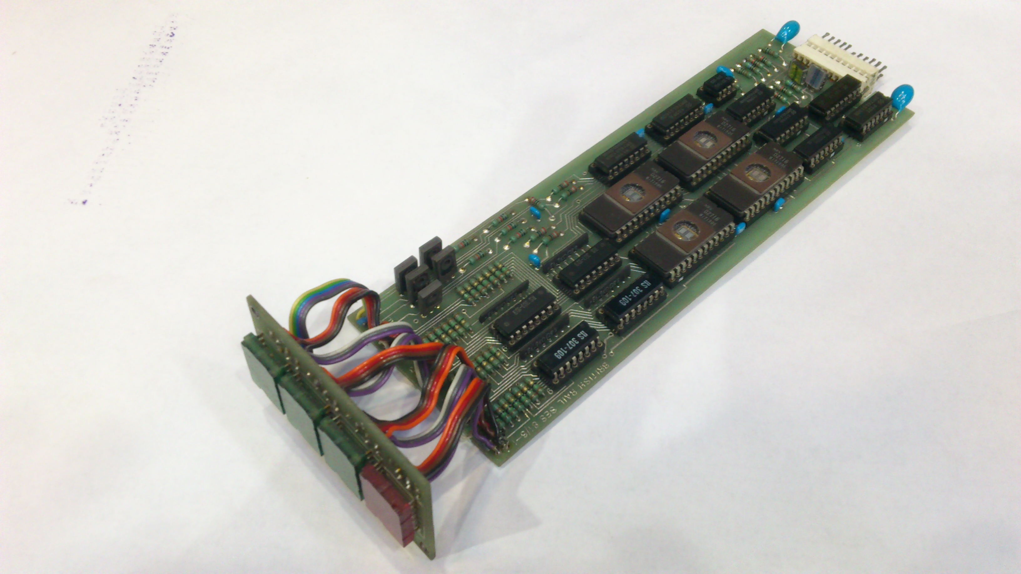
I redrew the circuit and updated it with my changes, then designed a PCB. It turned out a bit unussual for me as the components are mounted on both sides of the board.

The PCB with it's cutout for the display and a mockup of how it will look once built.


Before adding the IC sockets I thought I'd select the componets for the oscillator, to get close to the 80KHz I used a 33nF capacitor, a 270R resistor and a 120R selected on test.


At this point I soldered the headers onto the Pico and the PCB.


Unfortunately once the oscillator timing components were soldered on the board the frequency changed. I swapped out the 270R resistor for a 330R and replaced the 120R with a 100R multiturn preset potentiomenter. This made it very easy to calibrate.


Next the switches went on and the IC's went in.


Then the bit switches went on and the 4x20 display is fitted.


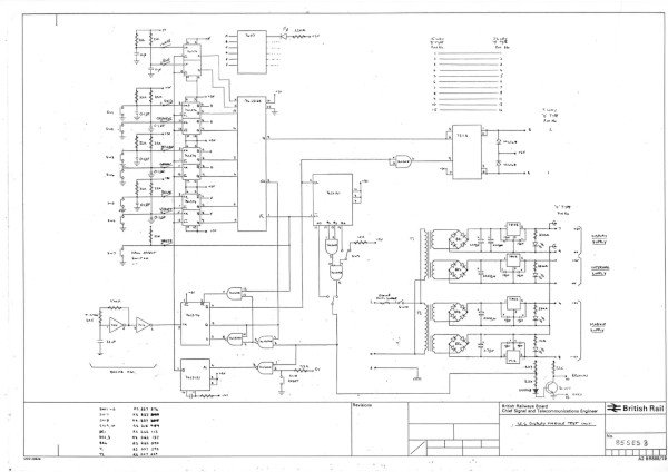
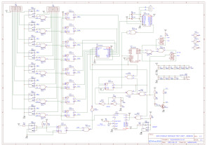
Circuit diagram for the original and new testers.
Testing commences.
The hardware logic worked as expected but there were a few silkscreen errors that I rectified by sticking new labels over the screen printing. It's not worth ordering new boards for just these errors. I can set up descriptions one character at a time on the switches using the character binary codes so it's on to writing the program for the Raspberry Pi Pico. With he Pico I'll be able to send the full four characters fast enough for the description to look as if they appear simultaneously.
Comparing the character set for the Aviemore single character display and the 8748 four character display shows that there are differences that will need to be catered for in the Pico.
The software is ready which can run several different tests, scrolling text or just simply displaying train descriptions. The Aviemore TD required a different character set so to simplify the final display with all modules running simultaneously I built a second test unit.


Display Tester Case
The case was formed in 0.9mm aluminium in two parts, the base which is just a plate and the top which will have the cutouts for the display and buttons. The sequence was to cut out base to size and drill the mounting holes. Then cut out the top sheet and marked up the drill and cutting details, I simply used a spare PCB as the template to mark the centres. Next I drilled the pilot holes and using a fret saw cutout the rectangular holes.
Then I fitted the panel to the circuit board to check and file any corners that didn't quite fit. I went on to fold the front and rear sections of aluminium and remove the protective film ready to sand and paint. Finally refitting the panels to the PCB's and stick on some feet.. Job done.


ScR Display Module Restoration.
First module up is the Aviemore single character display c.1980, this module was returned as faulty sometime in the late 80's. A replacement would have been sent out with this one, berth C335/C334, being put in the queue for repair. Well today (June 2021), some 30 odd years later, it has reached the front!. The circuit is based on the National Semiconductor MM5241 3972-bit static read only memory. These chips were available pre-programmed with different character sets, this one, the MM5241ABL is programmed with the ASCII-7 graphic subset.


The first picture shows the fault on the display, three columns not illuminating. Dismantling the unit and checking all the tracking on the pcb's and display front did not show up any cracked tracks or dry joints. Next I checked the display front connectors for discolouration, no problems there so it was time to bring out my logic probe. Checking the column drives did indeed show there was no drive signal so the obvious course of action was to reseat the 74LS138 in its socket which actually fixed the fault!.


Next up is the Cathcart display c.1987.
A similar story for this module, berth M142, came back faulty after years in service..


The fault, as can be seen, was a simple one. A faulty LED matrix and simply replaced.
Third up is from the Dundee TD display module build in 1985. This one worked straight out of storage. The subtle difference between the Dundee and Hight St modules is on the matrix PCB, the ribbon cable connector on the Dundee module is on the rear of the board.

Fourth up is from High St. TD c.1983.
I've been using this one for testing the Display Tester Unit so it's working ok. This display is based on the Intel D8748 micro controller and replaced the ROM based display module. It cut down the component count quite a bit.


Fifth up is the Hot Axle Box Detector in-line display used for Auchengray HABD at Motherwell SC. c.1981. Not many of these went into service, only two plus two spares!. The other twenty odd were kept in storage but were quickly superseded by the microcontroller based display. The circuit was based on the Aviemore single character display and multiplied up for four characters but this time we used 2716 EPROMs to hold the character set. It also removed the requirement for a -12V supply.
The module I had was the prototype which shows us trialing the red and green LED matrices, I seem to have miss placed it but luckily I have found a bare main board PCB.

I've started to update the design drawing with all the chip pin numbers and create a rough PCB overlay. I don't have the LED PCB which isn't a problem as I cannot find any information about the original LED's (DM75G12) so I'm in the process of designing a new front PCB to be used with the red versions of the High St./Dundee matrix. At the time we had settled on using red LED's to differentiate the HABD alarms from TD descriptions.
I'm also in the process of re-creating the character table to be programmed into 2716 EPROMs using the same character set as the aviemore single character display.

Programming the 2716** turned out to be fun, I had spent time typing the data into the S4 as I new it could program 2716's but it turned out not 21V versions so I quickly programmed a 2764 and copied into the stag PP39..problem solved..

The data for this display had been lost so when tested the .bin file will be added the system software zip file.
Display Assembly


The new LED matrix PCB and the 4 x LED matrix arrived enabling me to complete the assembly.
While waiting for these parts to arrive I built a basic case to hold the PCB's. It's not the same as the original which was made from steel, painted grey and some thumb screws for mounting.


Powering up soon uncovered a long forgotten 40 year old error in the circuit design and on the PCB, the 555 timer had its RESET pin tied to 0V preventing it from oscillating. I temporarily removed the leg from the socket and clipped it to 5V, that got it working.
The next task was to check the code in the EPROM, I just programmed one EPROM to allow me to check each character before programming the full set. Needless to say I found a few errors in my arithmetic which I easily sorted then I programmed*** all four EPROMs and tested the complete module.


** I'm confused by this..All the datasheets I can find for the 2716 state the programming voltage is 25V, virtually all the EPROM's available currently are labelled 21V. The S4 only programs 25V, the Stag is unknown but given it's age it's likely to be 25V. The EPROM programmed ok but have I caused it any damage programming it at 25V? Only time will tell when I erase and then try to re-program the EPROM.
*** re-programming worked ok! No damage done.
Taking Stock..
At the start of this project I wanted to restore at least one example of each of the ScR Train Describer Display Modules and have them all displaying a train description simultaneously. So far I have brought back to life five modules, Aviemore TD, Auchengray Hot Axle Box Detector, High St. TD, Dundee TD and Cathcart TD but there is one more to look at as it was used with one of our Train Decribers. This module was used for Hyndland TD extension around 1981 and was manufactured by Westinghouse Brake & Signal in the late 1970's, early 1980's.
Due to the differences in the module fonts and clocking requirements for the data transmission I had to build a second tester and now a third for the HABD module to allow all the modules to show changing data simultaneously. This third one is under construction but as usual I need to wait for a few parts to arrive. Lets hope I don't need a fourth tester for the Westinghouse module!
WBSL Display Module


The furthest back I can date this module is 1978 but it could be a bit earlier than that. The module uses ITT D17AL/G Dot Matrix displays which have built in shift registers/decoders, unfortunately I can't find any information on this display online..probably too old.
I remember repairing quite a few of these modules back in the day, mostly replacing the ITT display as a common fault with them was that one or more LED's would fail. Now that I've set up a module it has jogged my memory on how the data was transmitted to the module - The four characters are linked serially with each dot being a single bit so to send a four character description I'll need to send 144 bits of data. I recall that I had a crib sheet made up so I could look up a character and using my Display Tester send the data in six bit chunks. Without the ITT datasheet I'll need to recreate the data the hard way then program the RPi Pico with a few descriptions to show it off..this may take some time!.

An inside view.


It is very easy to create random patterns!!


I have worked out the bit pattern for each dot on the matrix and set up my first character. Ideally I would like to transmit the data a character at a time but it takes 36 bits and the tester can only transmit at 6, 7 or 8 bits. Each character will take six, 6 bit messages and a full TD description twenty four. It will be interesting to see how the Tester & Display will respond to this.


The basic character set is complete, letters, numbers, star and hyphen. Ideally I'd need yet another tester for this display but I think I'll share the HABD tester and just switch the transmission pair between the displays.


The third Display Tester is built but soon found out that the Pico could not handle two character sets - not enough RAM. I cut down the number of characters to display on the Westinghouse unit so I have a reasonable amount of descriptions to show.
The photos above highlights the differences between the two displays, the HABD only requires 6 bits/character and the WBSL 144 so when a character is sent in the WBSL format the last 4 (6 bit) bytes displays something sensible on both modules but if I send the data in the HABD format it is just jibberish on the WBSL module - not enough bits!. It really needs a fouth Tester..
And finally all the displays working simultaneously. The video also gives a little background to each one.