
Raspberry Pi Pico - Thermometer Switch
I have been wondering what to do to get started with the new Pico board so I thought I'd port my Thermometer Switch oringinally written in Python2 and run on a Pi Zero.
I first had to set up the Pico for Micro Python which the excellent 'getting started' turorials on the Raspberpi.org web site guided me through. Once I was ready to program I broke down
the Python2 program into it's basic functions:
1) Read the temperature
2) Display the temperature
3) Switch a Relay ON/OFF at a preset temperature
4) Log the ON/OFF times
5) Log any other useful data
There is one limitation with the Pico released, there is no active Real Time Clock so logging the correct time and date will need to wait. (Update - March 21 There has been an update
to Thonny/Pico to implement the RTC so now if it's plugged in the host computer it'll automatically update the RTC on the Pico - this is great but has the limitation of the time is lost
between unplugging the host and plugging into an independant PSU.
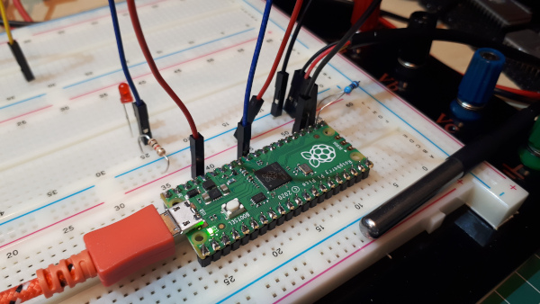
The first thing I had to do was to see if I can use an external sensor rather than the in-built one as I want to sense the room temperature and not that of the case it's mounted in. Luckily there is a
1wire and DS1820 module available for the Pico which made it easy to use an external sensor. I then programmed the internal LED to flash when sampling the temperature and an external LED to simulate the
Relay ON/OFF output.
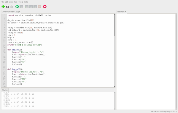
Logging - at the moment I've set up the logging as before, logging ON/OFF, above 34 Degrees, below 8 and 0 degrees. Although I have managed to create a time stamp using the utime module I haven't
found a way to set the date or time..still looking..(sorted with the Thonny update)
To display the temperature and the ON/OFF switch setting I'll be using an I2C 1602 display.
I have just found out that as a first time user of the 1602 display it is not staight forward to program. First call was to the Pico Getting Started book as it shows a two line display in the
example of I2C. As it turns out this guide is only for the SparkFun SerLCD screen and not the common displays that are on sale on eBay or AliExpress. A fair amount of Internet searching and a bit
of trial and error resulted in a working display. Now I know how to do it is quite easy.
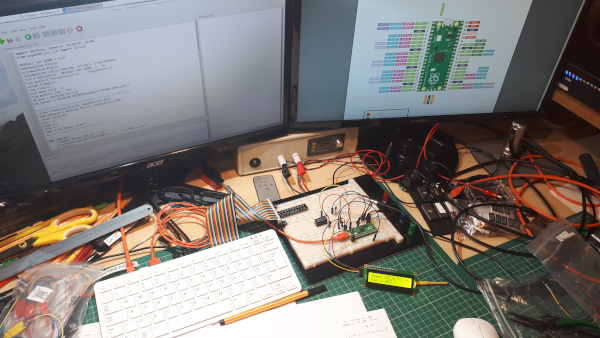
Got it talking..
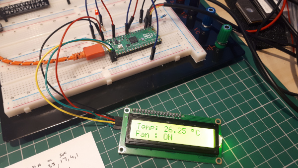
Tidied up the the script and added a 'Watchdog' flashing star so I can tell the Pico hasn't froze. I have also added a relay to switch on at a preset temperature, a bit 'old hat' but it works.
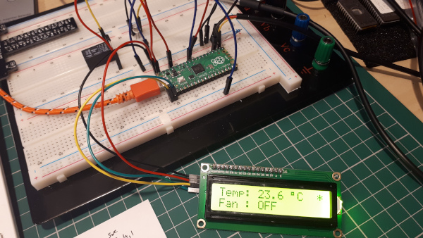
Soak Testing..
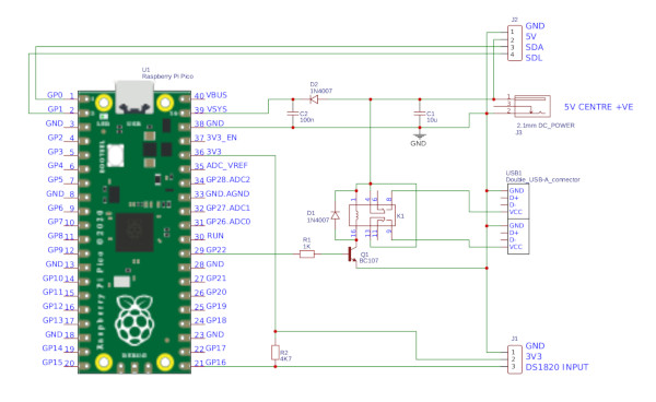
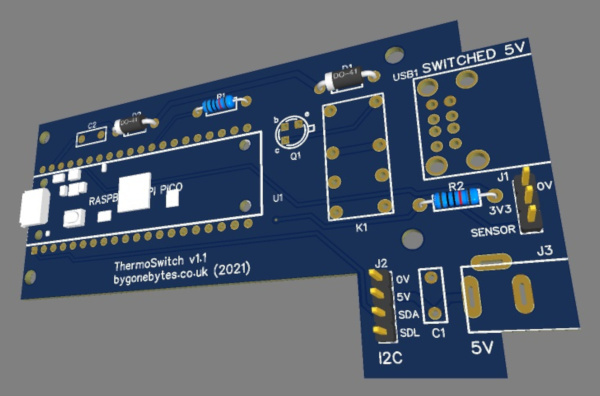
Next I drew a CAD design and produced a circuit board for the Pi Pico and supporting components. The display will mount on the back so it'll become a single module. When complete the overall
unit size will be a lot smaller than the earlier design from 2017 and displays more information.
The Script
The script reads the DS1820 and displays the temperature on the 1602 LCD display, it also displays the current state of the switched output and the time and date. It also logs certain
information i.e Fan ON/OFF and temperatures above and below preset levels mentioned above. The log file is a comma separated text file (CSV) to make it easy to import into a spreadsheet.
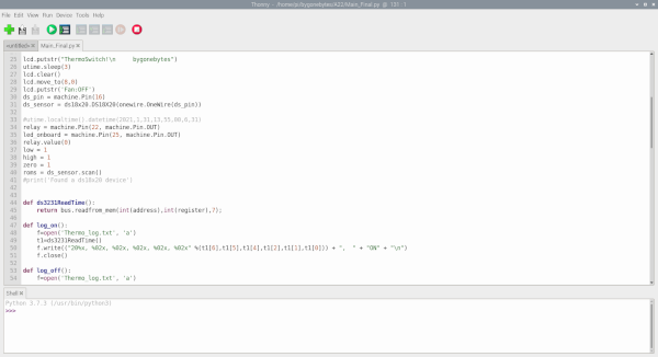
![]() ThermoSwitch script for Raspberry Pi Pico.
ThermoSwitch script for Raspberry Pi Pico.
The Case
During the closing down sale of Maplin Electronics I bought various project boxes of which I have selected this one. It's just the right size for the display and the small PCB.
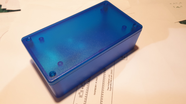
I cut out the hole for the display but it wasn't without its problems, The lid of the case has moulded standoffs which i thought would get in the way of the display so I tried to cut one out
but that left a stress mark on the front. I have also ordered some dark bolts to mount the display so there not as obvious as the silver ones, so a bit of tidying up to do.
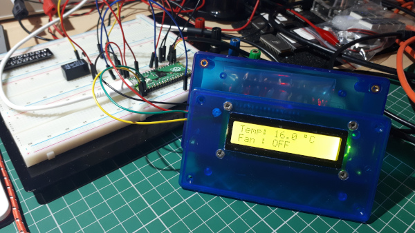
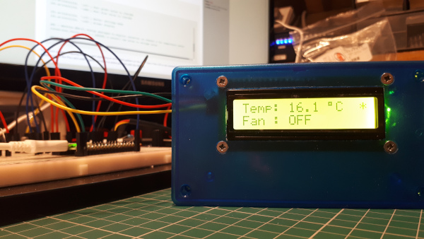
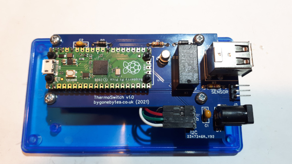
The PCB assembled with the Pico, relay etc. and mounted on the rear of the display. I used 5mm standoff's to mount the Pico on the PCB then connected the 8 pads (only 7 are needed) from the Pico to
the PCB. This will make the Pico secure for inserting the Micro USB connector and at the same time easy to replace.
I made a few mistakes on this board, on the I2C bus I crossed over the SDA and SDL signals and on the USB port I crossed the 0V and 5V due to an error on the USB part I selected to used in
the drawing. The SDA/SDL was easily sorted by crossing the link jumper wires however fixing the USB was a bit more involved as I had to make up an external crossover cable. Although the ThermoSwitch is
complete I am unhappy with the errors on the board so I have corrected them in the drawing above along with improving the PCB labelling and sent off for a new PCB.
The old and the new - both running together for a few weeks until I receive the new board then I'll finally switch off the old unit and recover the Raspberry Pi Zero W to use in a future project.
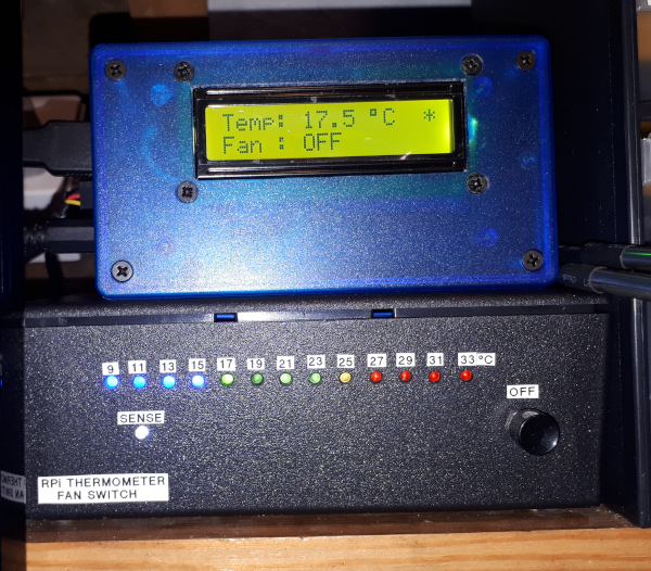
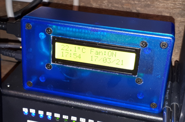
In the last few weeks the Pico has been updated to enable the on board RTC so I have been experimenting with the switch and it now displays the time/date and properly logs the data. As I use
the VSYS input to power (via a diode) the Pico I can also plug in the USB cable to set the time. With this setup the time is not lost when unpluging the USB again although if all power is
lost from the ThermoSwitch the time and date will be lost - an external battery backed RTC is required or another diode and battery pack applied to VSYS would hold the clock time during
power outages.
With the new PCB and battery backed RTC delivered I can now finish the project. I re-wrote the program to read the time and date from the Waveshare RTC and formatted the output for
both screen and log file.
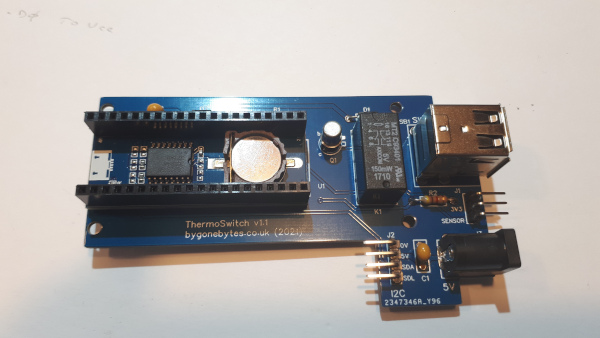
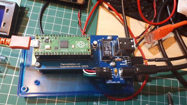
The time and date are now retained during power outages and with the new board correcting the display I2C bus and the 5V on the USB out sockets the unit is ready to take over the cooling of
my Einstein@home Pi's.
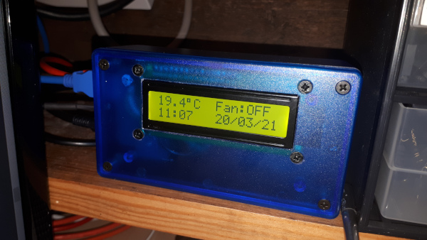
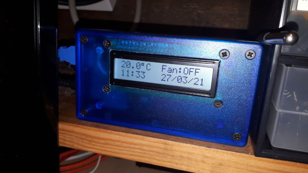
And one last change - I didn't like the yellow display background so I replaced it with white.
Note 1 - I found that the first sample of the temperature sensor always returned 85 degrees, this caused the output to switch on the fan for one second and log the high temperature point. To stop
this blip from happening I replaced the splash screen delay with a loop that reads the temperature and discards the results. Meanwhile I have a feeling the problem with reading the wrong temperature
is a loose connection on the sensor/PCB, I will change the standard header to a locking header to see if that fixes the issue.
Note 2 - Replacing the header socket arrangement to a locking header fixed the spurious temperature readings.