Electron Clone v3.0 - Adding Econet
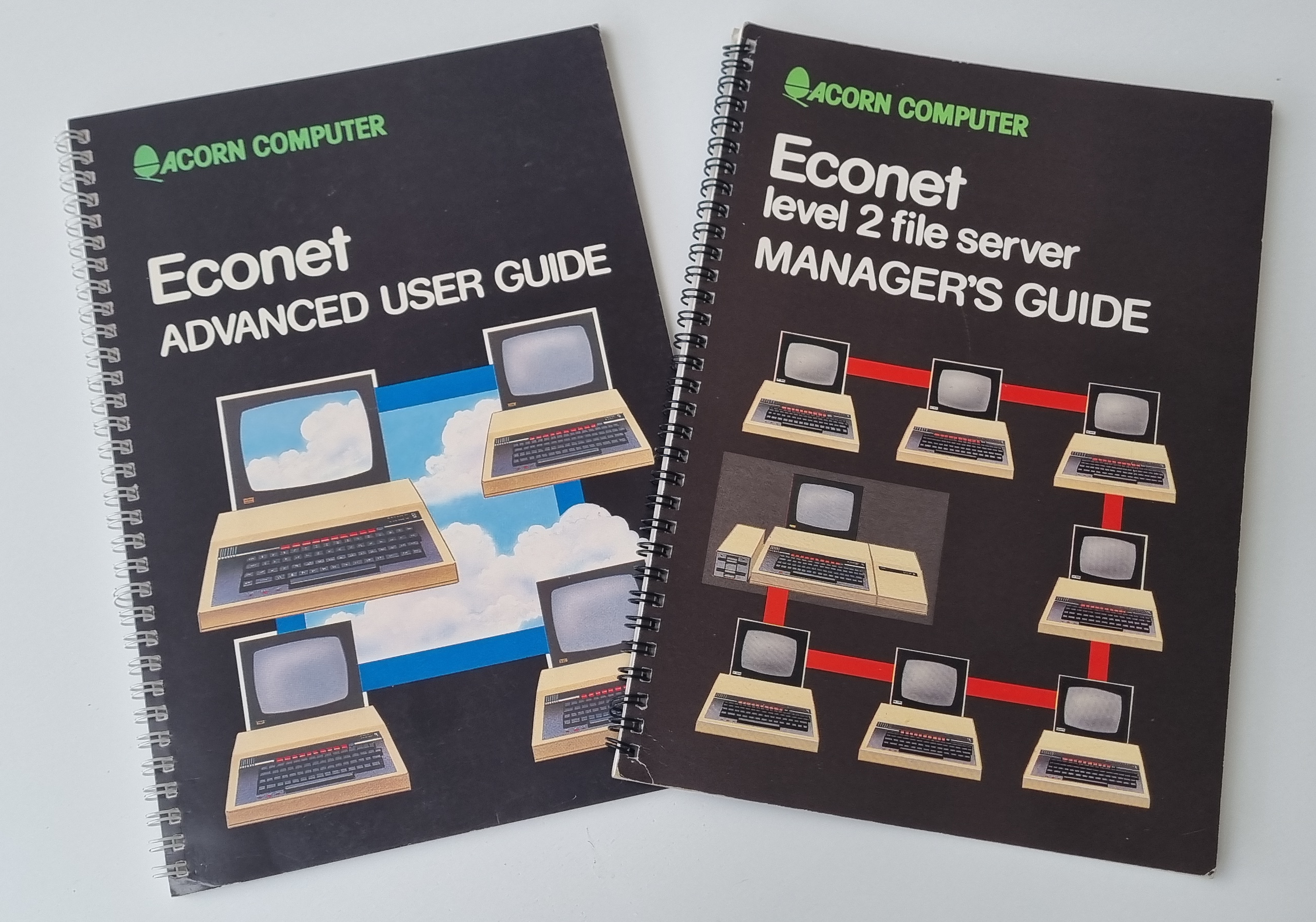
July 2025 - At a recent ABUG Scotland meeting I picked up on a comment that I should add Econet, the Acorn propriety network. Over the following few days I couldn't help but give it some thought and some research on Stardot. I new from posts a few years ago that an Econet interface had been designed for the Electron and wanted to see how it was achieved. I read through two threads on the Econet interface, one on the development and a second on the build. The second thread had the design included so I downloaded that to see if I could fit the design directly on the Clone PCB.
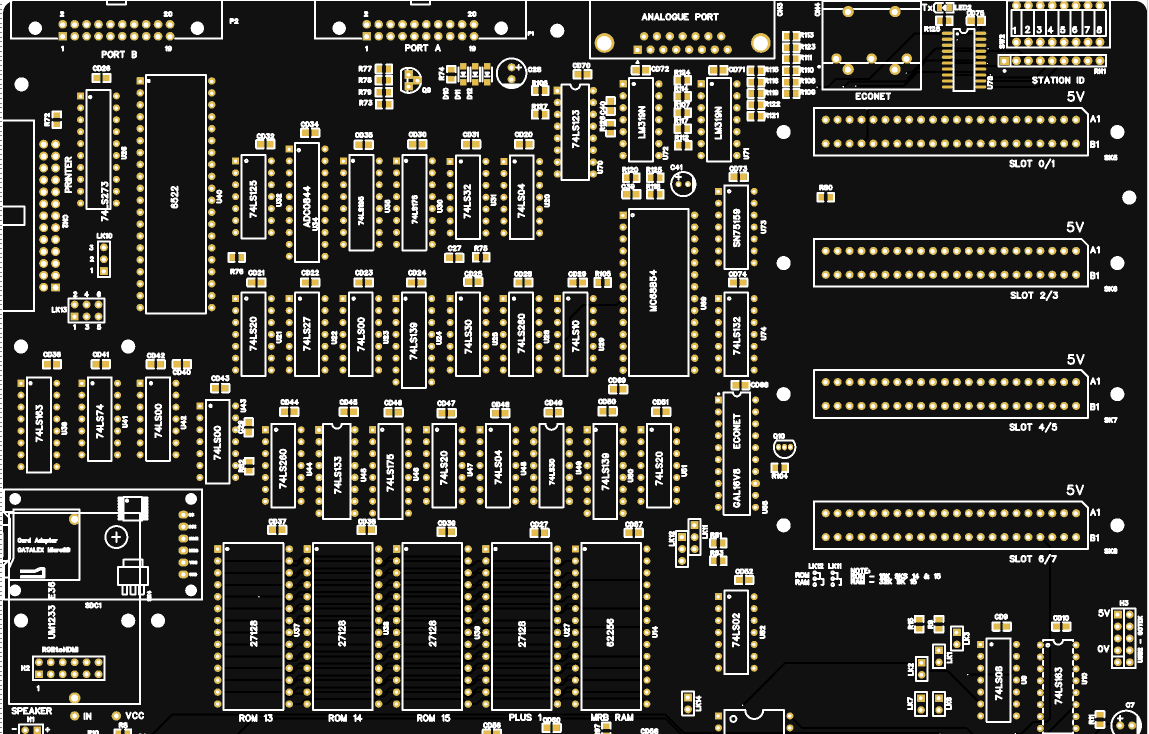
The Econet interface was designed as a cartridge that plugs into a Plus 1 slot and I think someone also designed a cartridge case for the PCB. I could just use the cartridge but this is not the challenge. The circuit can be broken down into various building blocks - the Advanced Data link Controller (ADLC), The I/O interface, the station ID buffer and the glue logic including ROM 13 ROM 0/1, 2/3 decoding and Flash ROM.
The posts I read on Stardot:
Econet Cartridge development
Econet Build Instructions
Econet Bridge with Integrated Econet Module, Econet Clock & Termination
The clone already has ROM 13 on board and with building the circuit directly on to the Clone PCB I also don't need to include the Flash ROM and its decoding circuits. So before I go any further I will reach out to the designer of the cartridge to check it's ok to incorporate it into my clone and hopefully get some source documentation to enable me to make the changes needed.
Meanwhile I'll read some books from my collection, wonder how I'm going to get eight more IC's and a DIN connector on the circuit board and find out more about Ken Lowe's Econet Bridge.
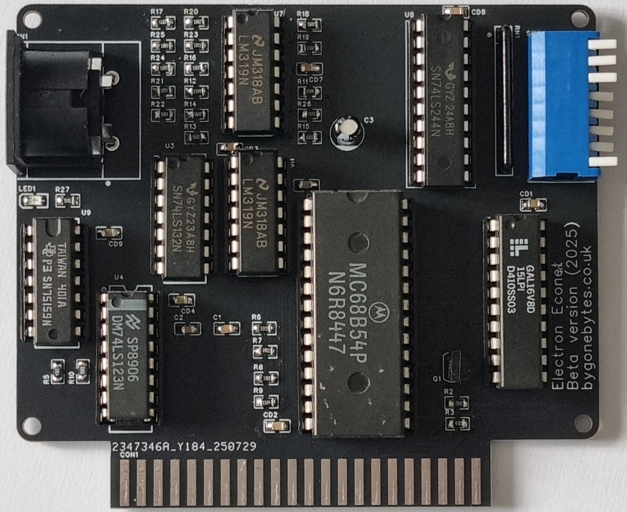
Before I commit to ordering a new clone PCB I decided to test the new circuit and glue logic on a much smaller PCB and when I'm happy with everything I'll make the changes to the Clone PCB.
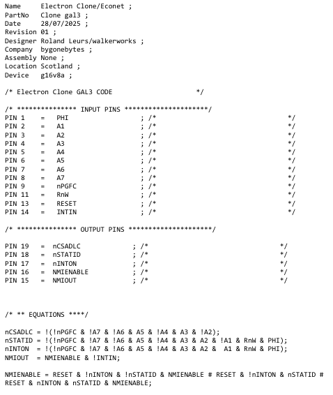
The first item to update is the GAL glue logic. The sample logic was built on a different system to the one I use which is WinCupl.
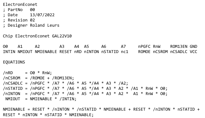
So I had to convert it to the syntax used by WinCupl and then removed the ROM decoding. This allowed me to use a smaller GAL, a 16V8 instead of the 22V10.
The simplest PCB to test the reduced circuit and GAL logic on is a small cartridge which I put together in EasyEDA and ordered from JLCPCB - the board cost of just £3.65 for five.
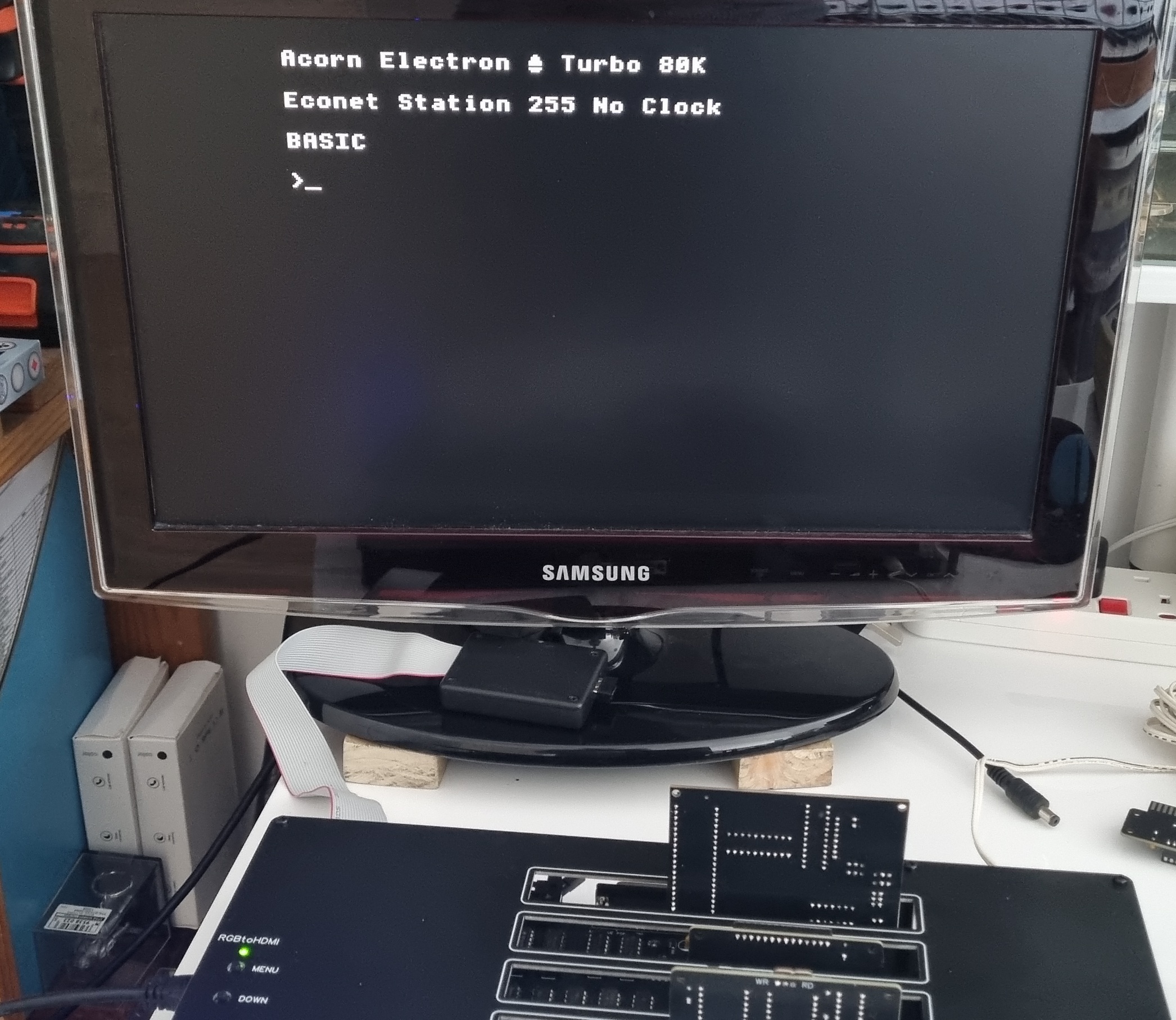
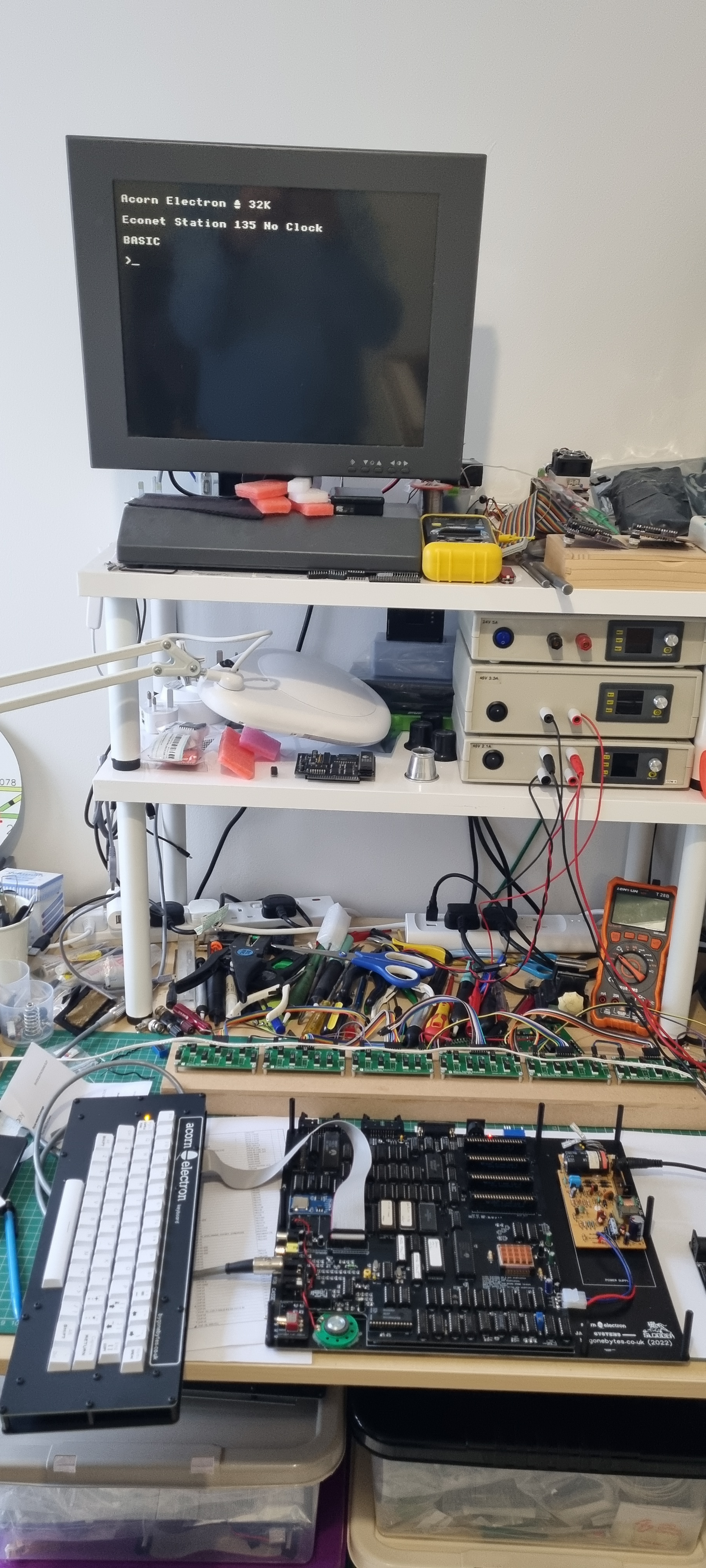
Next up was to blow the NFS ROM and install it in ROM 13. The response on the screen is as expected without an Econet interface plugged in. No Clock and the Econet station set at 255 (&FF)
August 2025 - The test PCB arrived but not all the parts. I'm only missing the ADLC so I've built the card minus that.
Even without the ADLC I can plug it in into the Electron to see if the Station ID is read OK. This will prove a small part of the GAL programming.
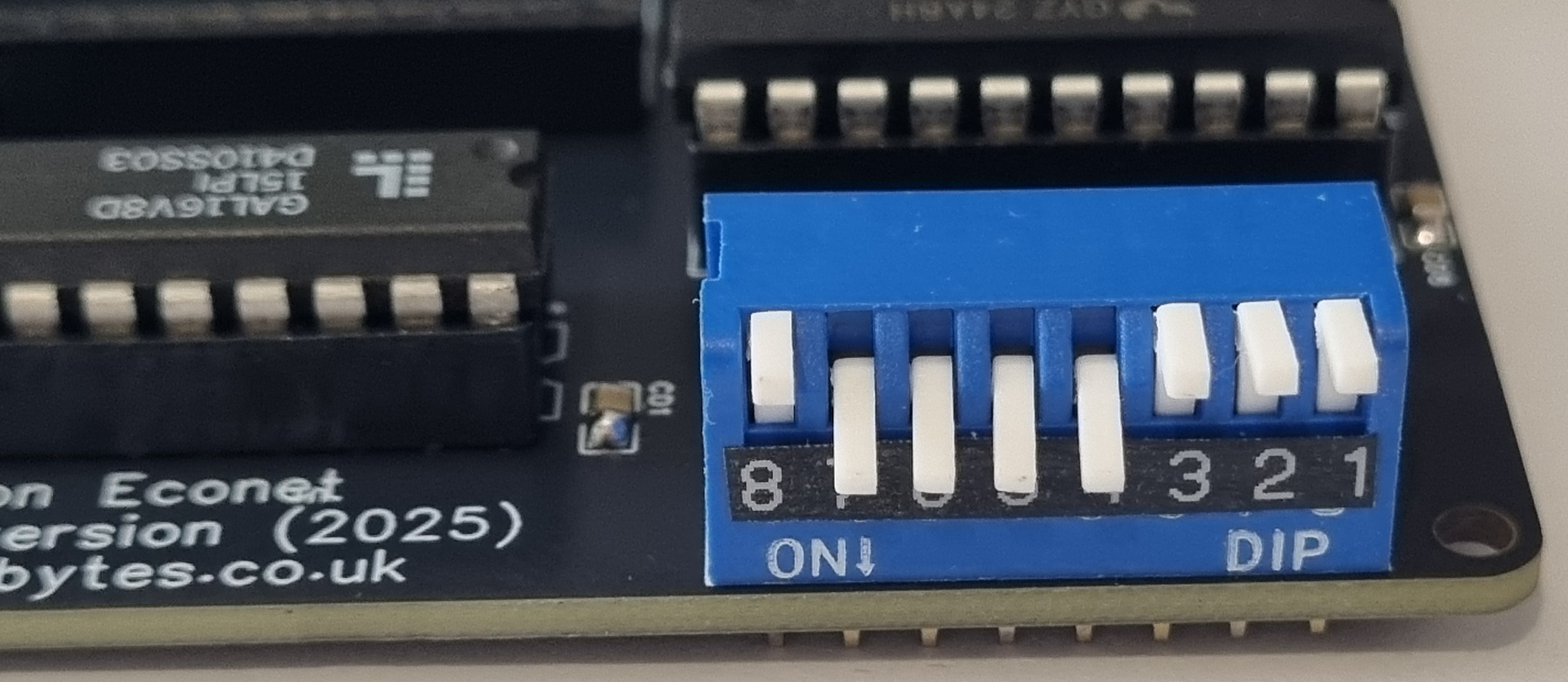
To set the Station ID the switch needs to be set, ON for a logic '0' and OFF for a logic '1'. I set the switches to 135 or binary 10000111.
Switching on and the Station ID is indeed 135. Once I receive the ADLC and the Econet Bridge I'll be able to test the clock and data transfer.
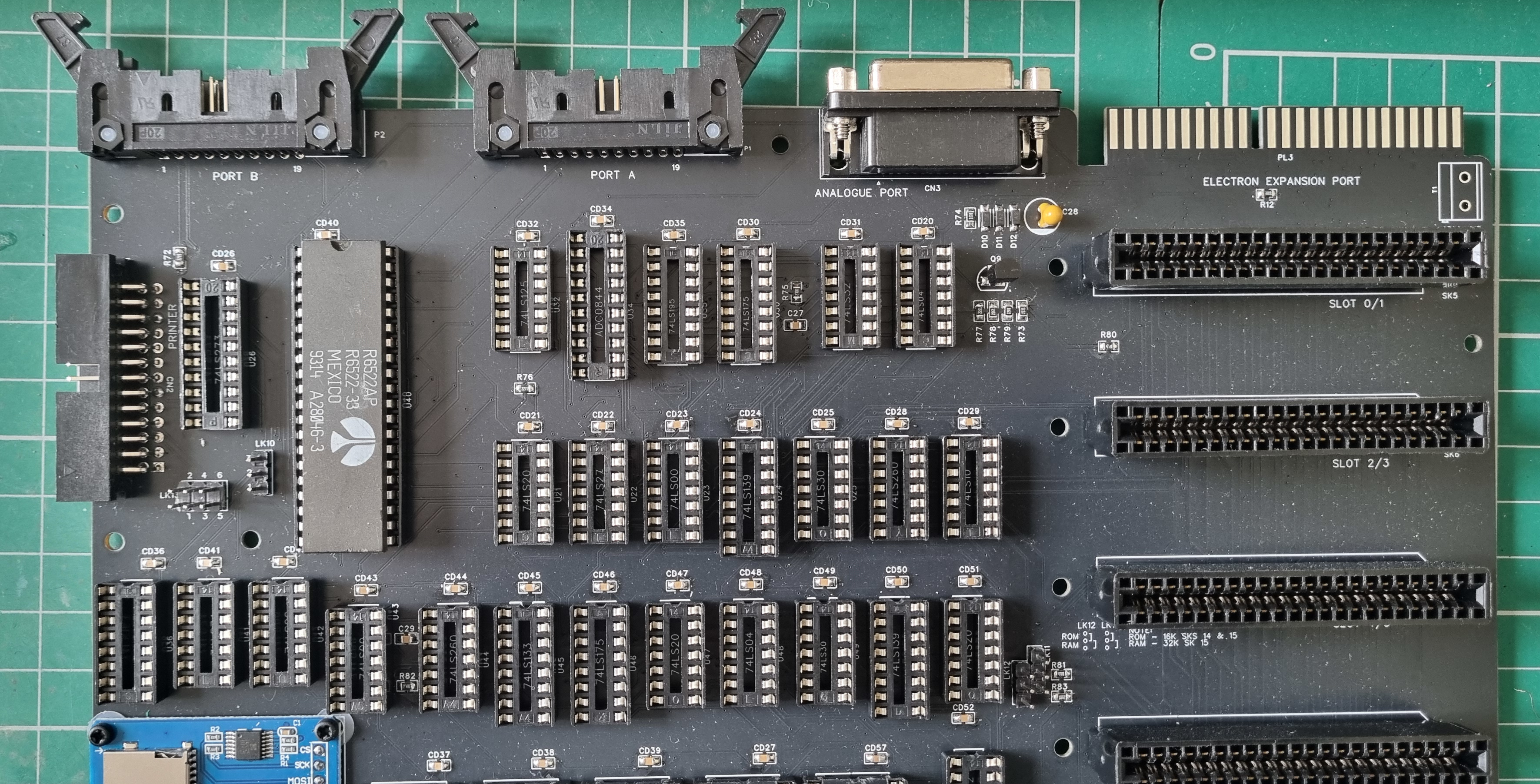
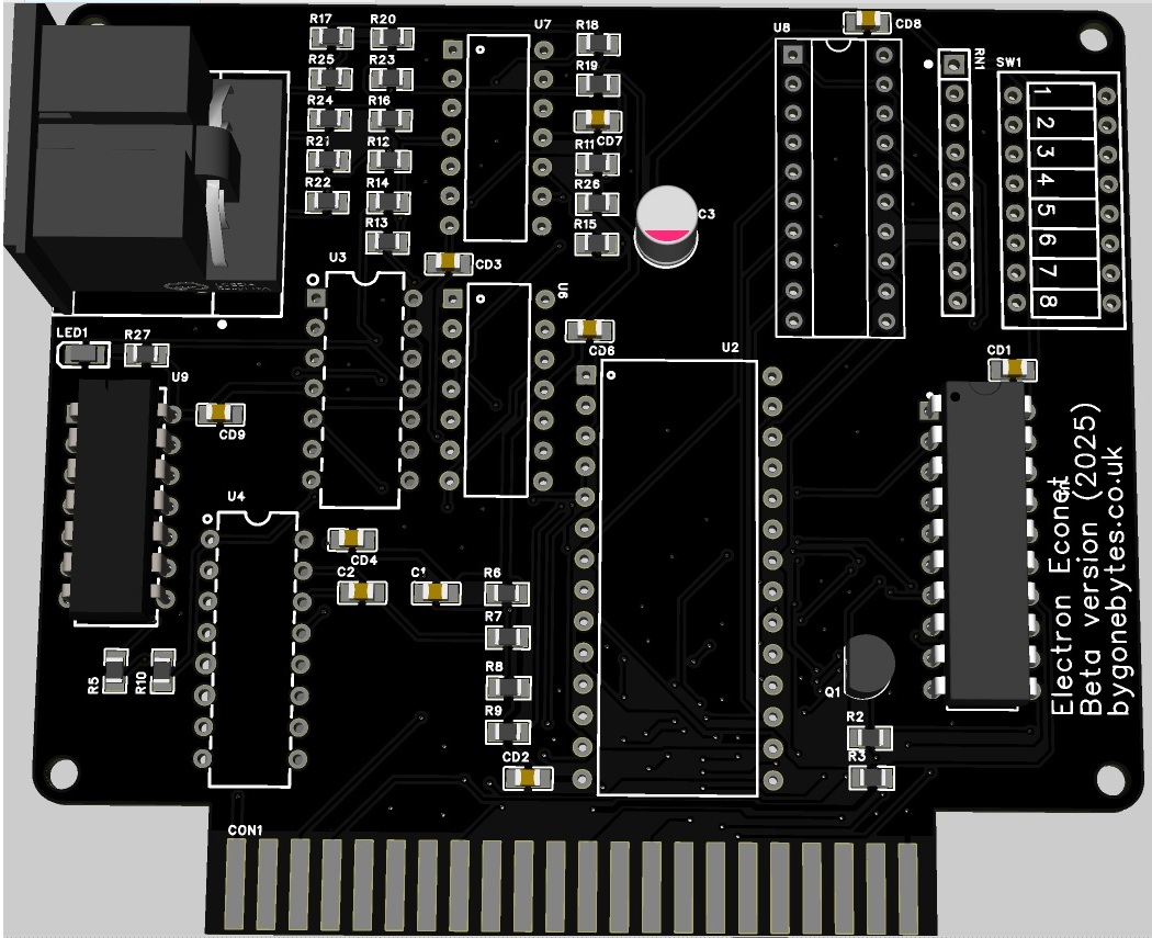
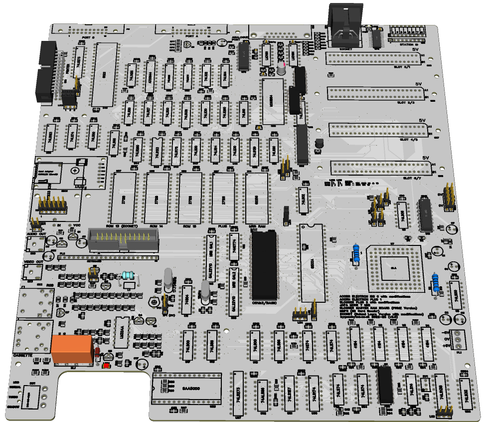
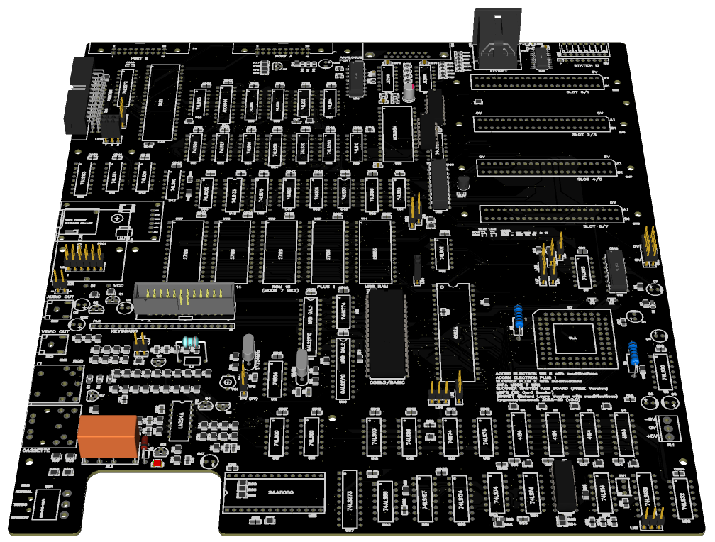
While I was waiting on the test PCB I made a start on the Clone board, it took a lot of re-arranging but I managed to squeeze it all in. I finally made the decision to remove the expansion port as I needed the space for the Econet DIN socket and station ID switch. I also had to relent on only using through hole IC's, the lack of space meant I had to use a surface mount 74LS244. Laying out the tracking is ongoing.
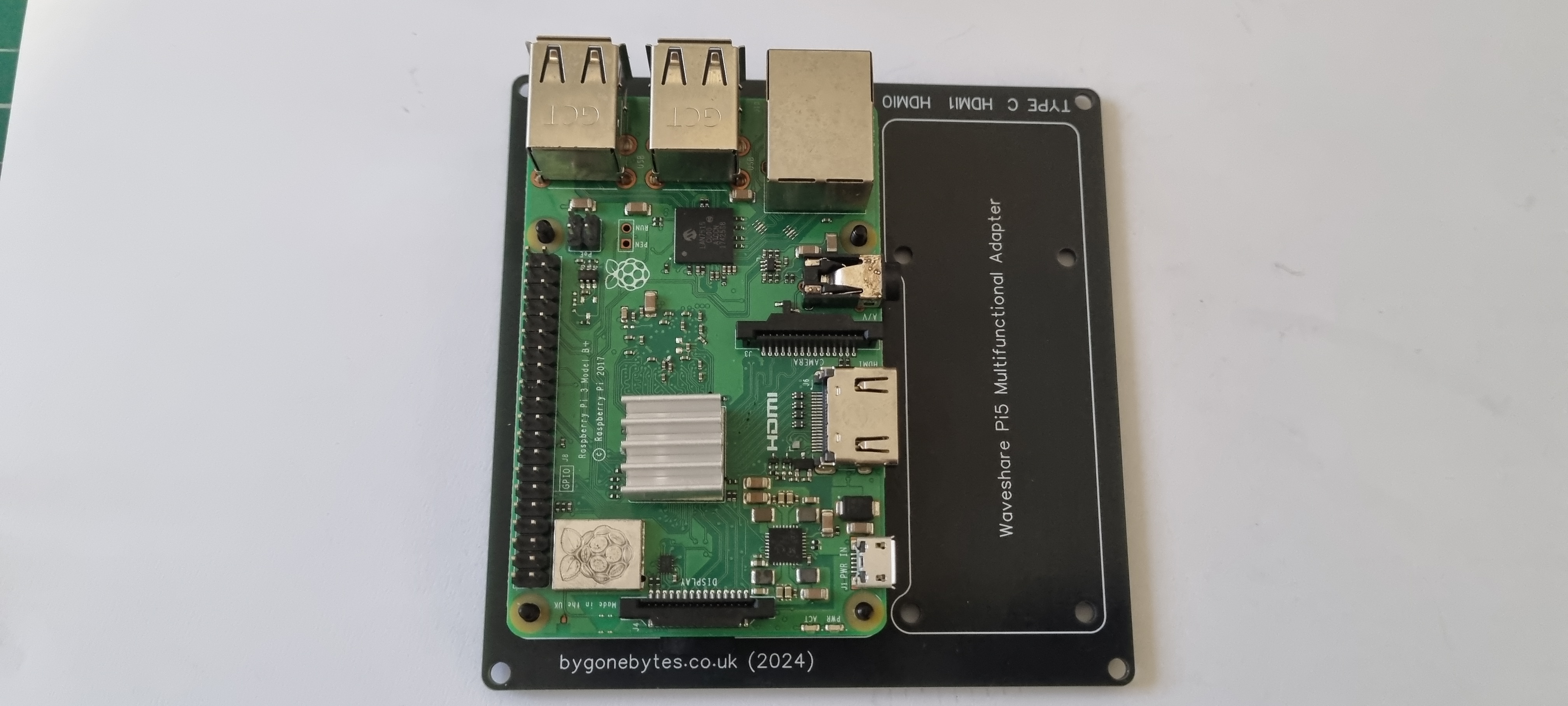
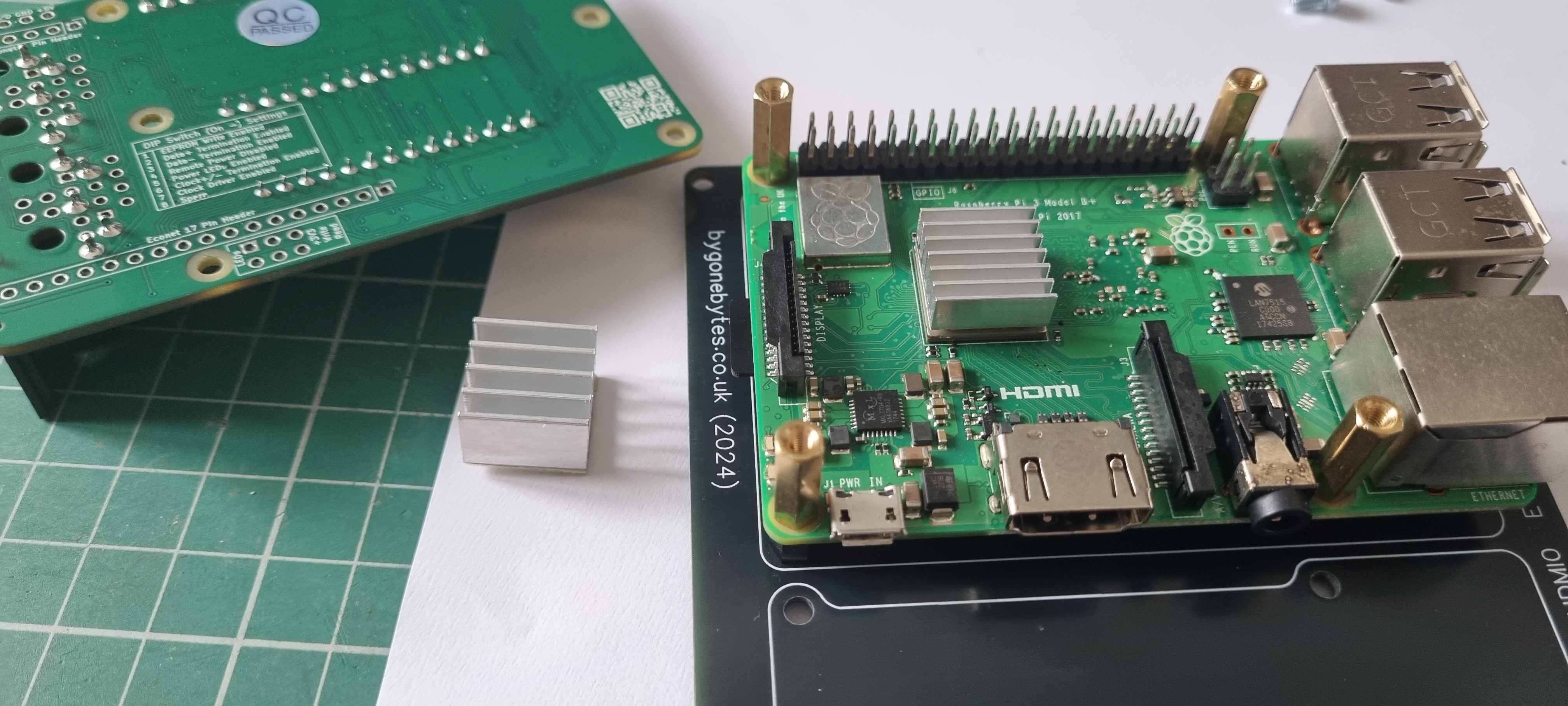
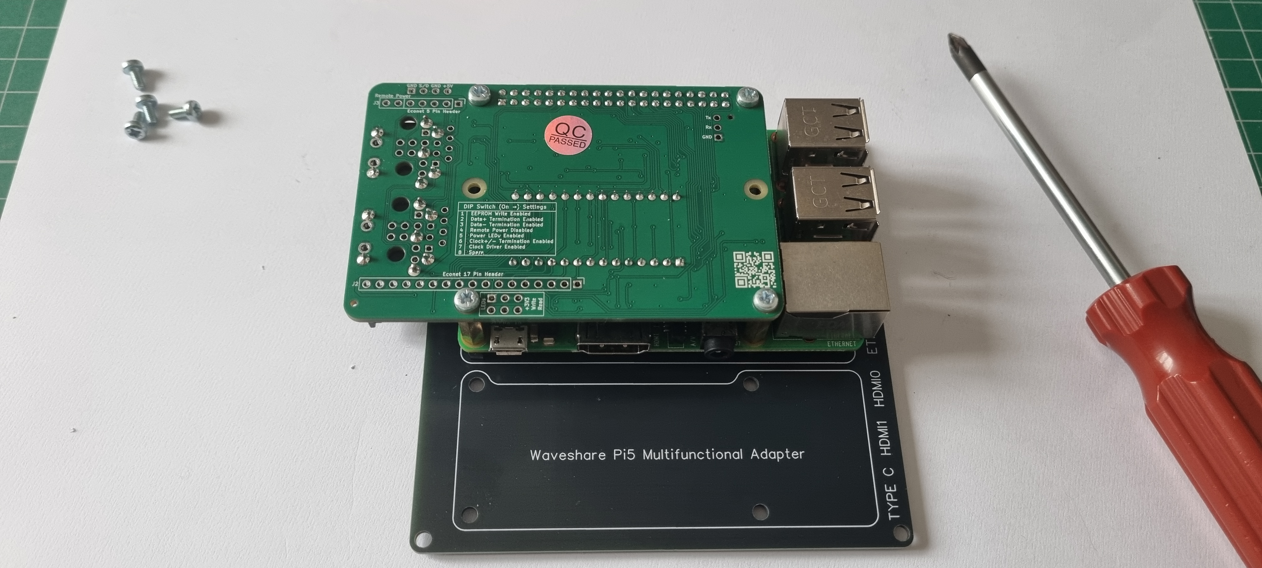
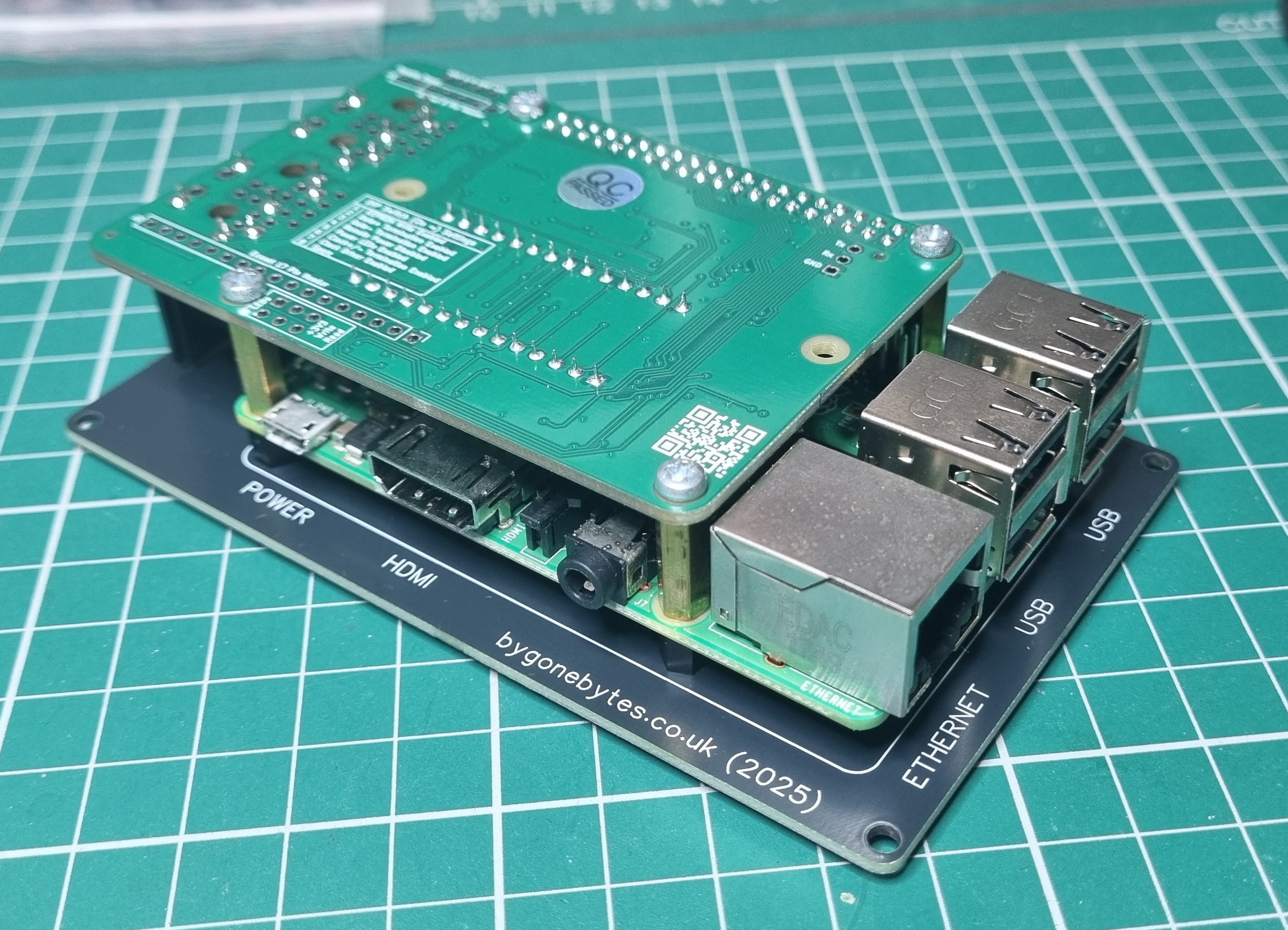
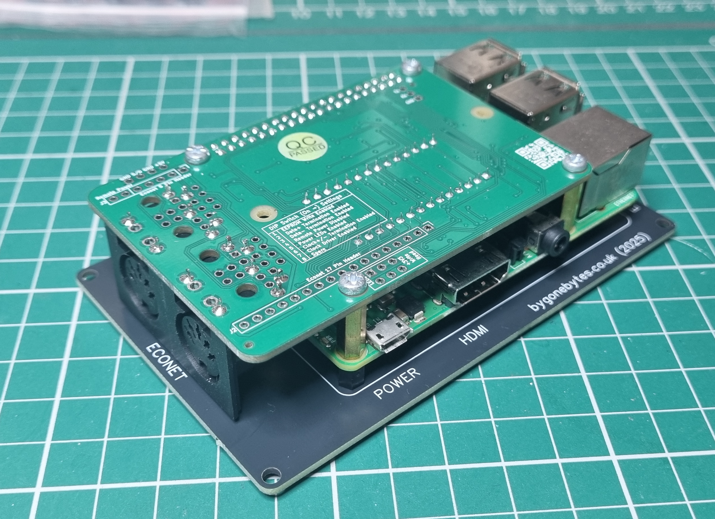
11 August 25 - Some more preparation work. In anticipation of the arrival of the PIEconetBridge HAT I have prepared a Raspberry 3B+ in accordance to the installation notes in the stardot thread linked above. So far I have created an SD card with the Lite version of PiOS with SSH enabled but not the wi-fi as I'll be using a wired ethernet connection. The installation of the Econet software has to wait for the PiEconetBridge to arrive. Temporarily I'll be using my Raspberry Pi5 case until I get around to making something more suitable.
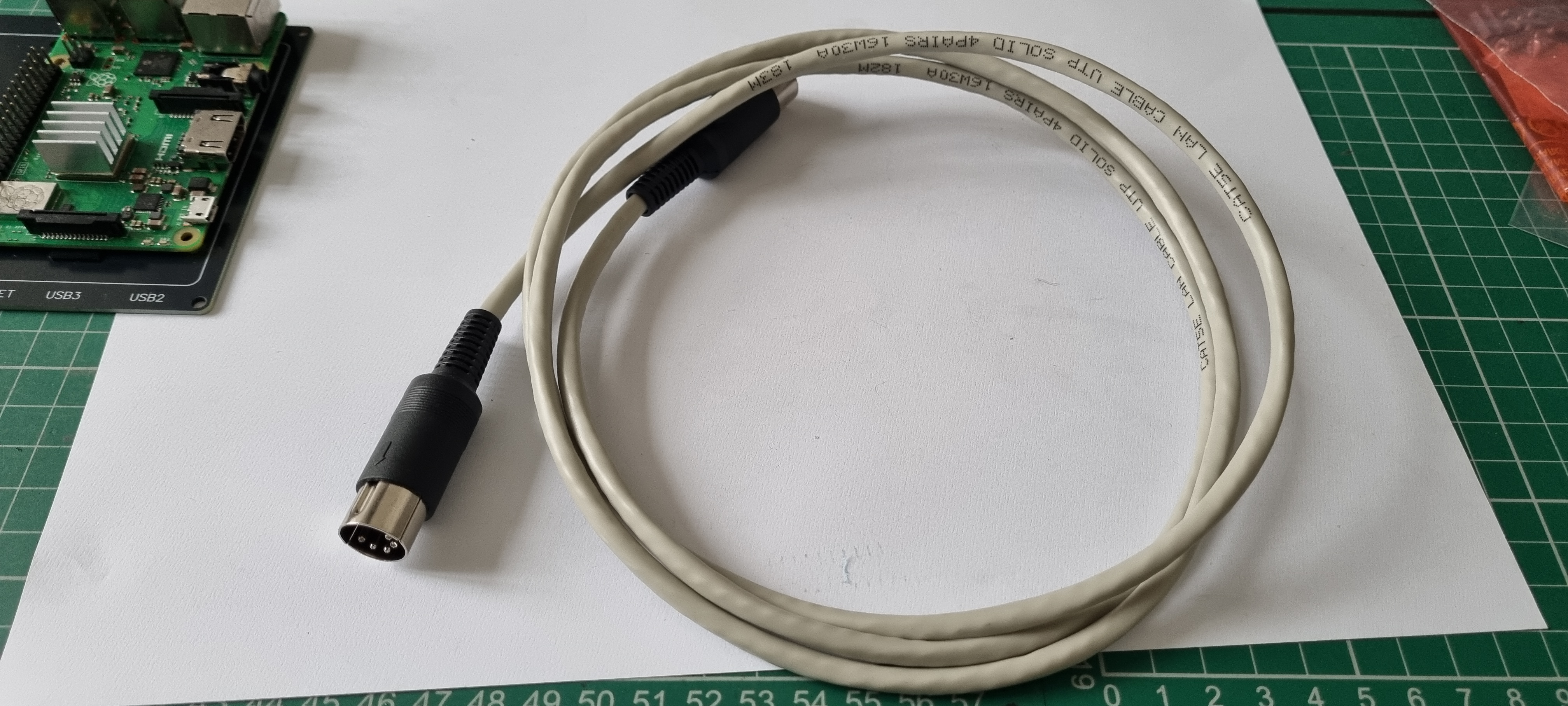
I have also made a DIN lead using CAT 5E cable with the twisted pairs connected as per all the guides, 1 & 4 Data, 3 & 5 Clock and 2 Ground.
I have finished all the tracking on the new v3 PCB so it is ready to go to JLCPCB barring any last minute changes. I should change the colour of the board for this version. I've had purple, blue, red and black so I'm thinking white for version 3 but I'm unsure...
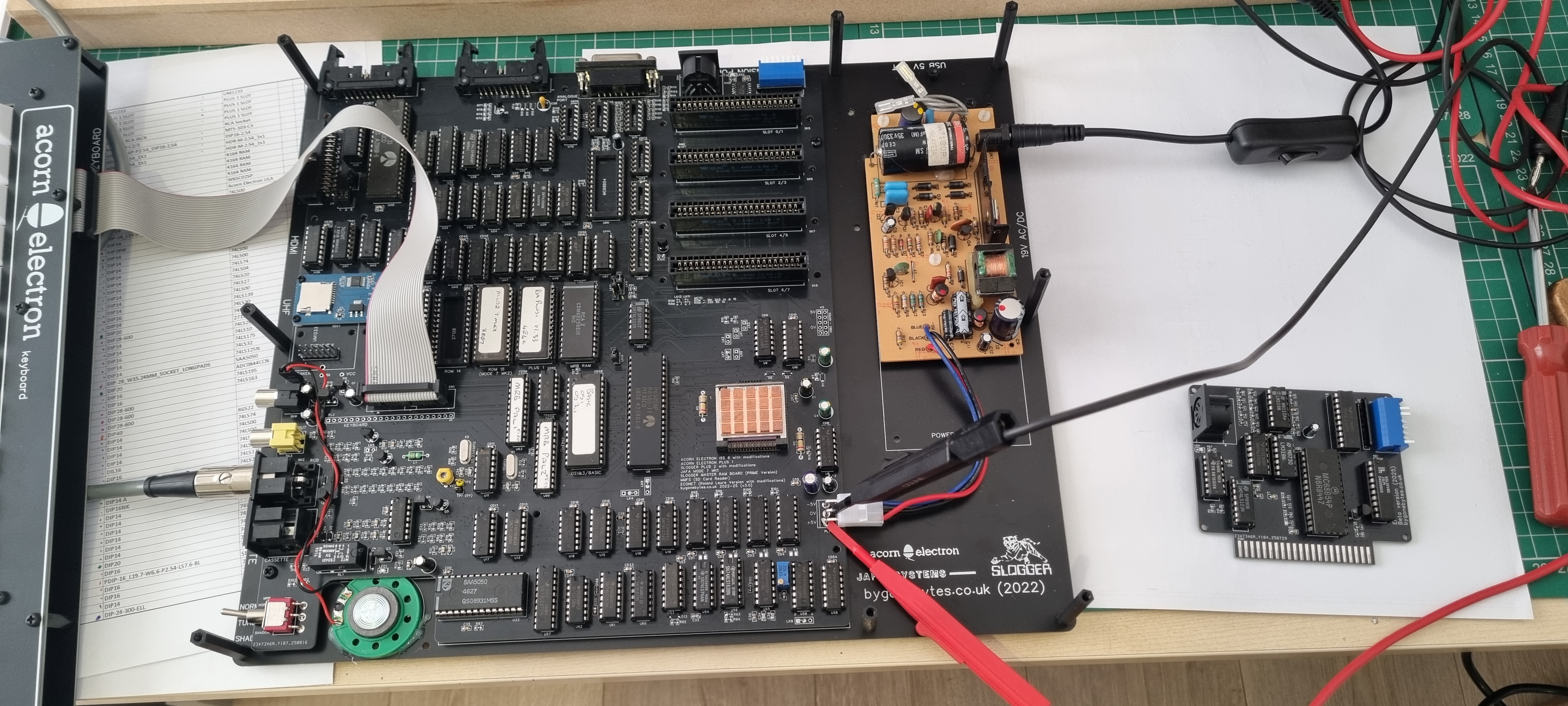
And lastly for now the ADLC has arrived...so the test board is ready.
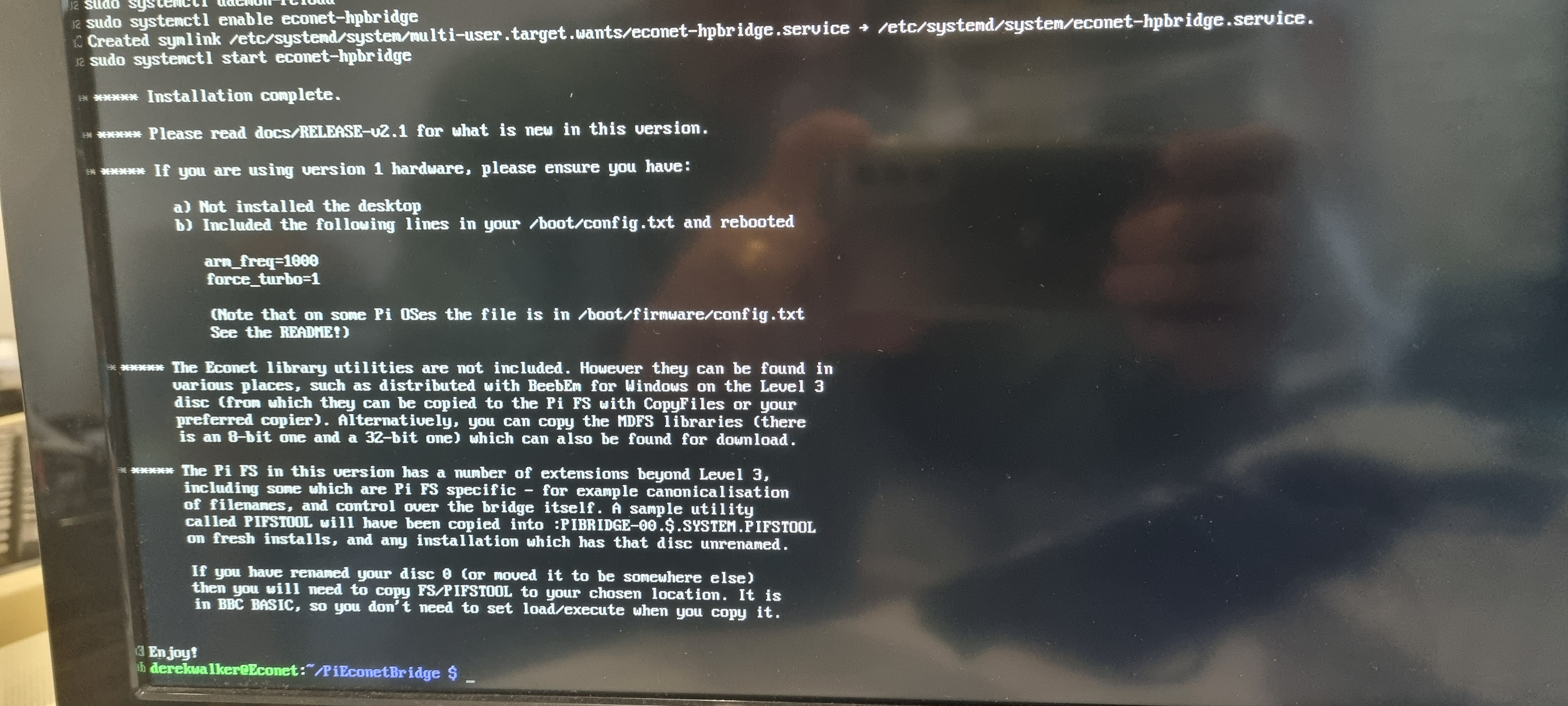
12 August 2025 - the PiEconetBridge HAT arrived and I installed it on to my pi3b+ and connected it to the network and switched on...
Continuing to follow the sofware installation instructions I tried to log in via SSH using PuTTY on my Pi5 but PuTTY would just instantly close. (I later discovered PuTTY isn't compatible with the Wayland interface used in PiOS - I'm not going to change it to X11 so that's another app out the window.) So as to not get side tracked I just plugged in a monitor and keyboard into the pi3B+ and on I went until I completed the installation of the 'libexplain' etc libraries. At this point a reboot would tell me my IP address was 127.0.0.1 and it was impossible to log into the Pi. The address should be my local network IP and look something like 192.168.1.xx
Start again! A new install of the PiOS lite but this time I didn't bother with the 'update', 'full-upgrade' instructions and it installed flawlessly.
Back to the Electron now. Connecting it to the PiEconetBridge with the DIN cable I made earlier and switching on I still get 'no clock' there are so many things I could have done wrong so I started by putting the scope on the DIN connector and as expected there was a good clock signal. At this point I had to consider what could be wrong with the interface card. I re-checked the GAL logic and the circuit tracking, I even reduced the clock pulse by 50% to 100KHz but no joy. Lastly I checked the high speed comparators, the LM319N, no signals were getting past them so I checked my bag of components and I found that one out of the ten I bought was a different make so I tried it in the position that affected the clock path and it worked.
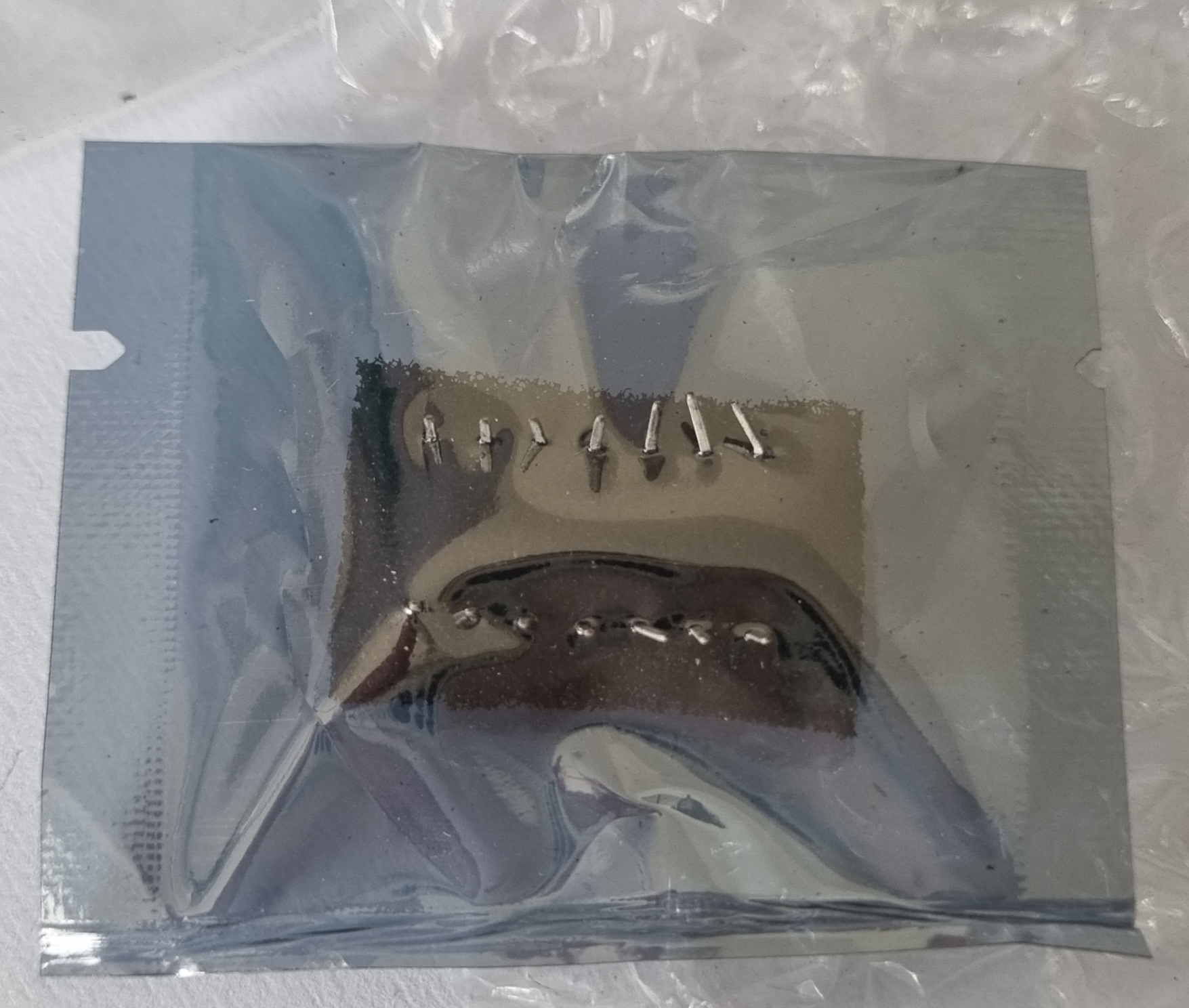
Testing the other nine LM319N's and they're all faulty or are re-numbered IC's! I need one more for the Data input so that is now on order.
15 August 2025 - The LM319 arrived! a bit mangled but it got here and it still worked.
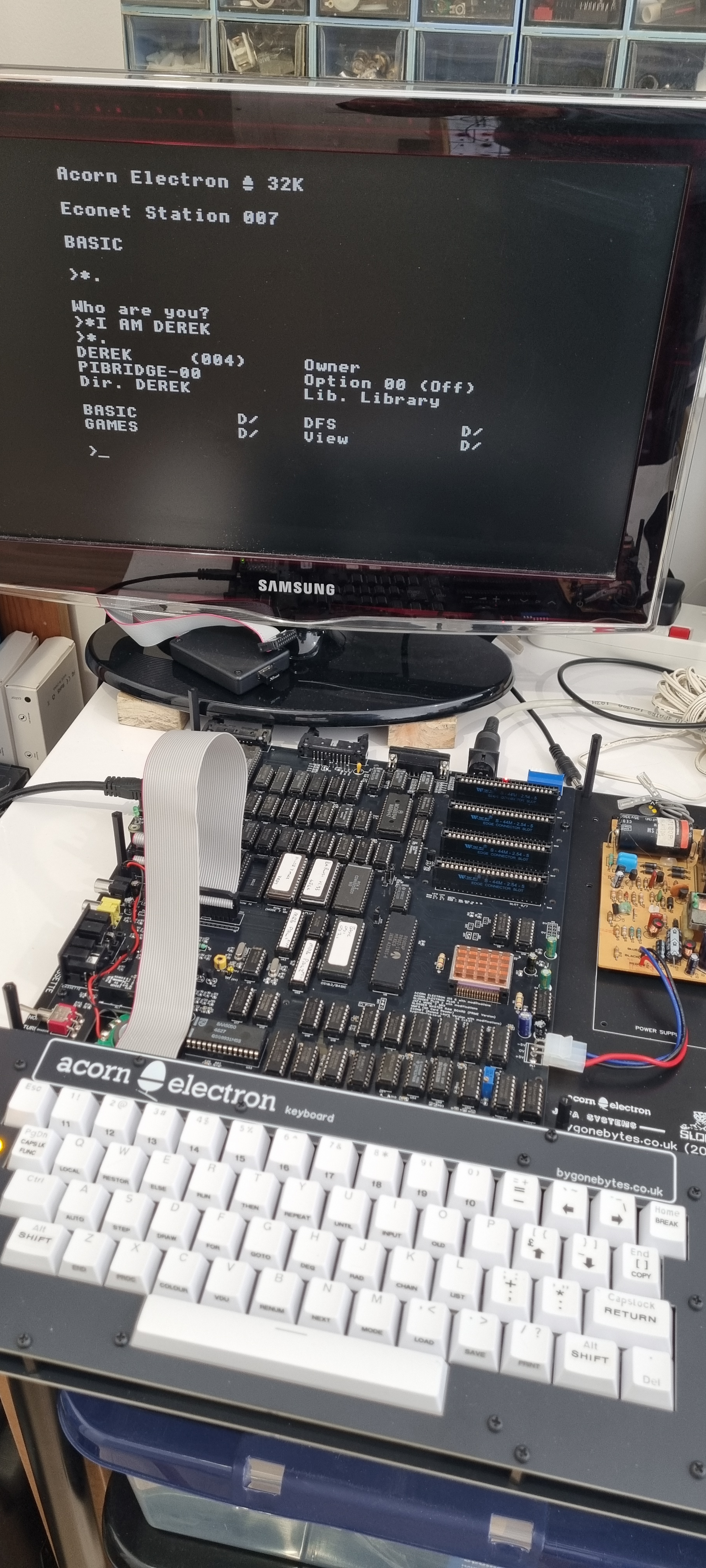
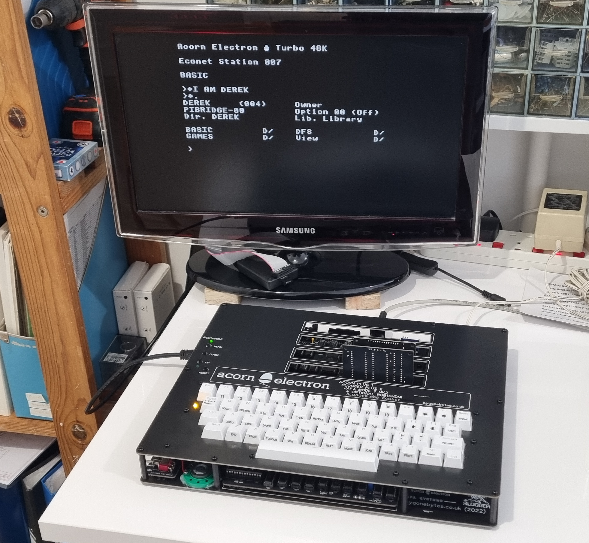
Anyway I now have a network of one client..
The good news I didn't break anything with my changes to the circuit and GAL firmware so I can send off for the new clone PCB's.
Things I'm finding out about along the way:
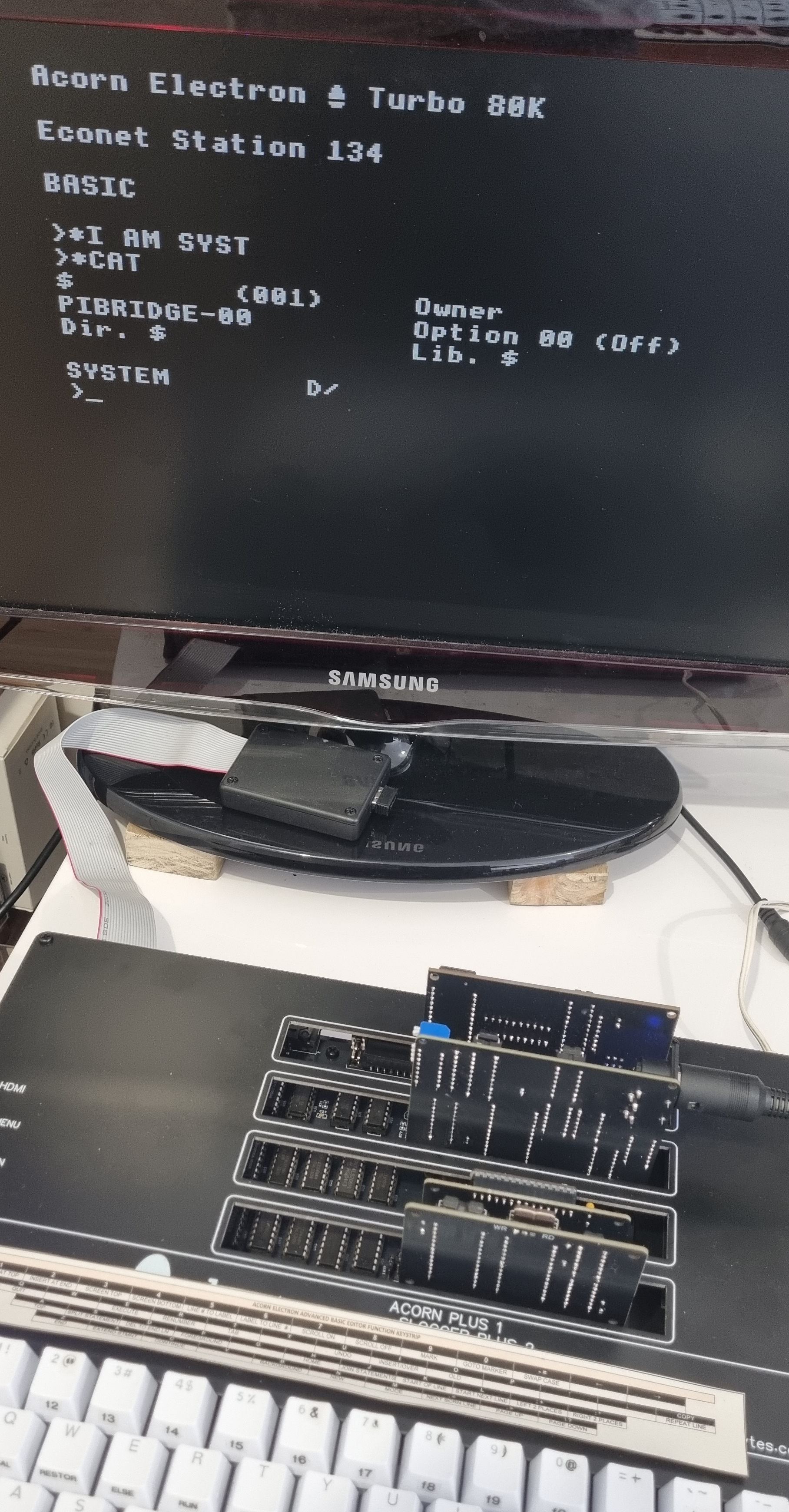
The Econet works very well in all modes of the Master RAM Board and can switch easily between MMFS and NET filing systems for transferring files etc.. I've yet to try the Pegasus 400 DFS.
It is not fully compatible with the E2P, SAVE and LOAD to the file server doesn't work.
The MODE7 MK2 doesn't play well either with the NET filing system.
The RPi 6502 second processor in the Advance Tube Interface works a treat.
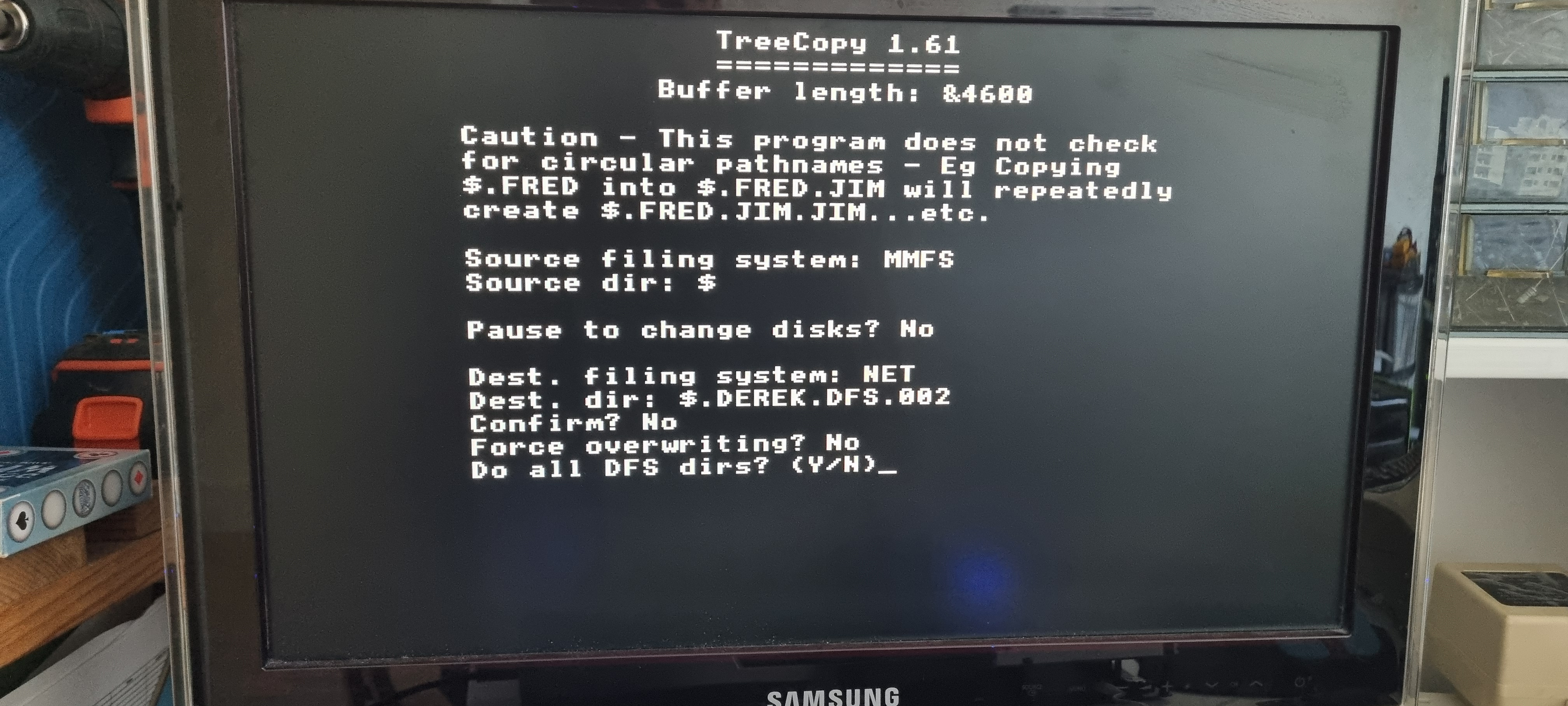
The Treecopy program in the RH Plus 1 ROM is great for copying files between MMFS and NET filing systems - not tried DFS but I'm sure it'll work fine.
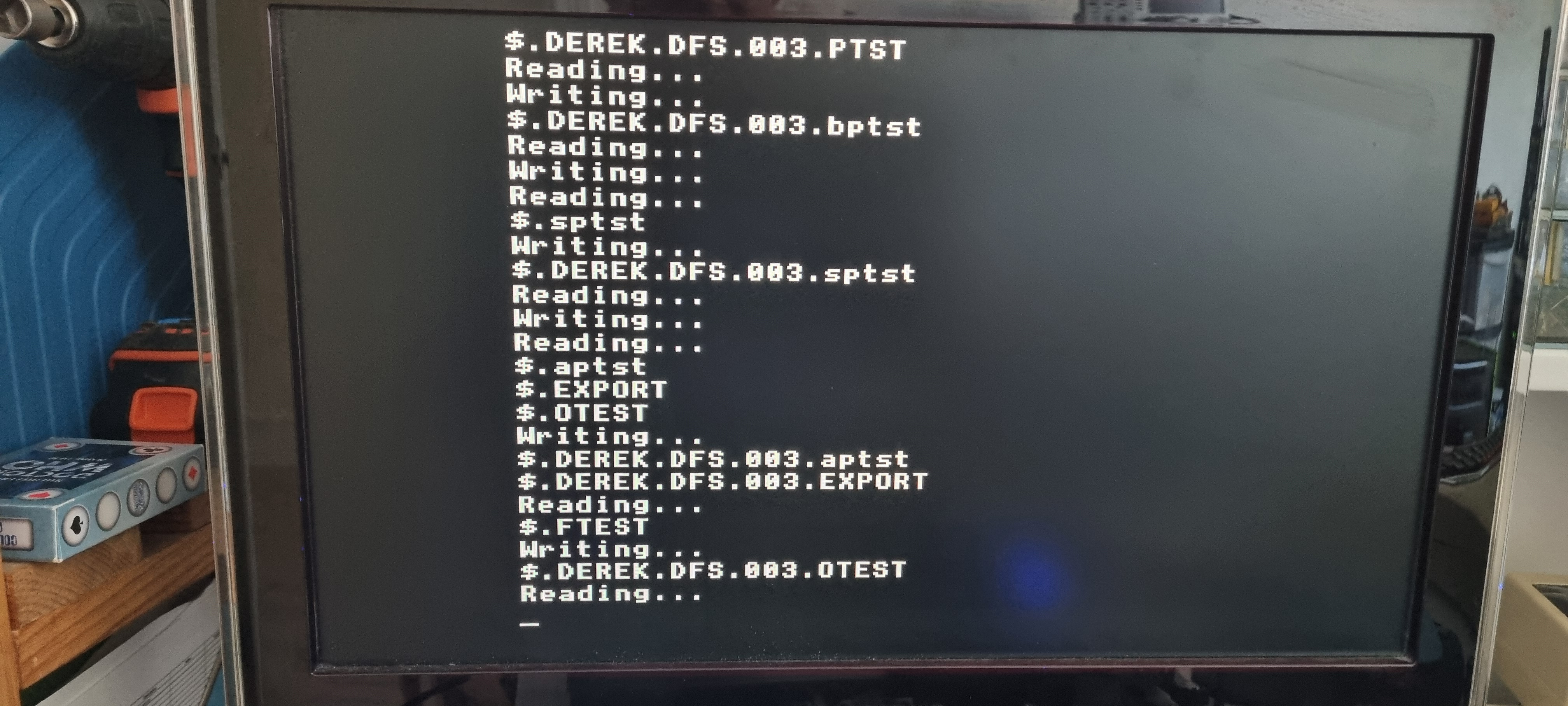
The NET filing system does not allow a file and a directory to have the same name in the same directory - something DFS does. I discovered this when copying the Technocad NovaCAD !boot disc.
The PiEconetBridge in my make-shift case runs at a CPU temperature of 61 degrees when lying flat, only 49 degrees when standing on end - better ventilation - room temperature was also high at 25 degrees due to current heatwave. The Pi only has a 10mm sq. passive heatsink so under normal room temperatures it'll be fine to be left on 24/7.
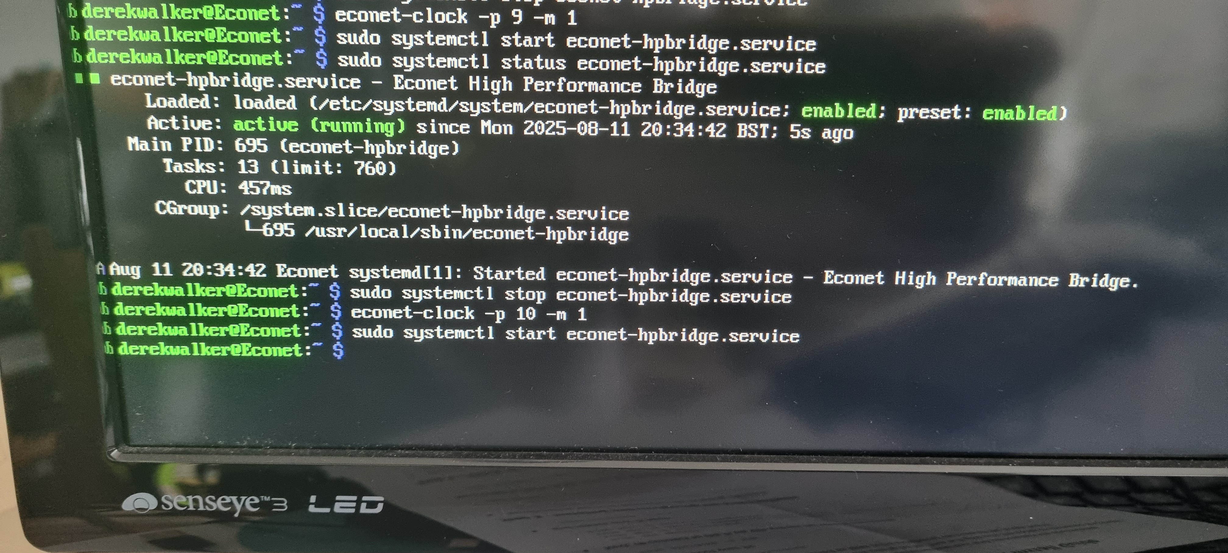
Setting up the clock frequency: As I understand it the clock frequency determines the data rate between the client and the Bridge, unfortunately I didn't take a note of the default settings before I changed them. Looking through on-line documentation I believe this to be 200KHz.
The highest clock rate I could set it at for reliable operation of the Electron in Normal mode is 142KHz. I tried increasing that to 166KHz and that worked reliably in Turbo and Shadow mode. I didn't try to increase it beyond that as it has to be set for the 'worst case'.
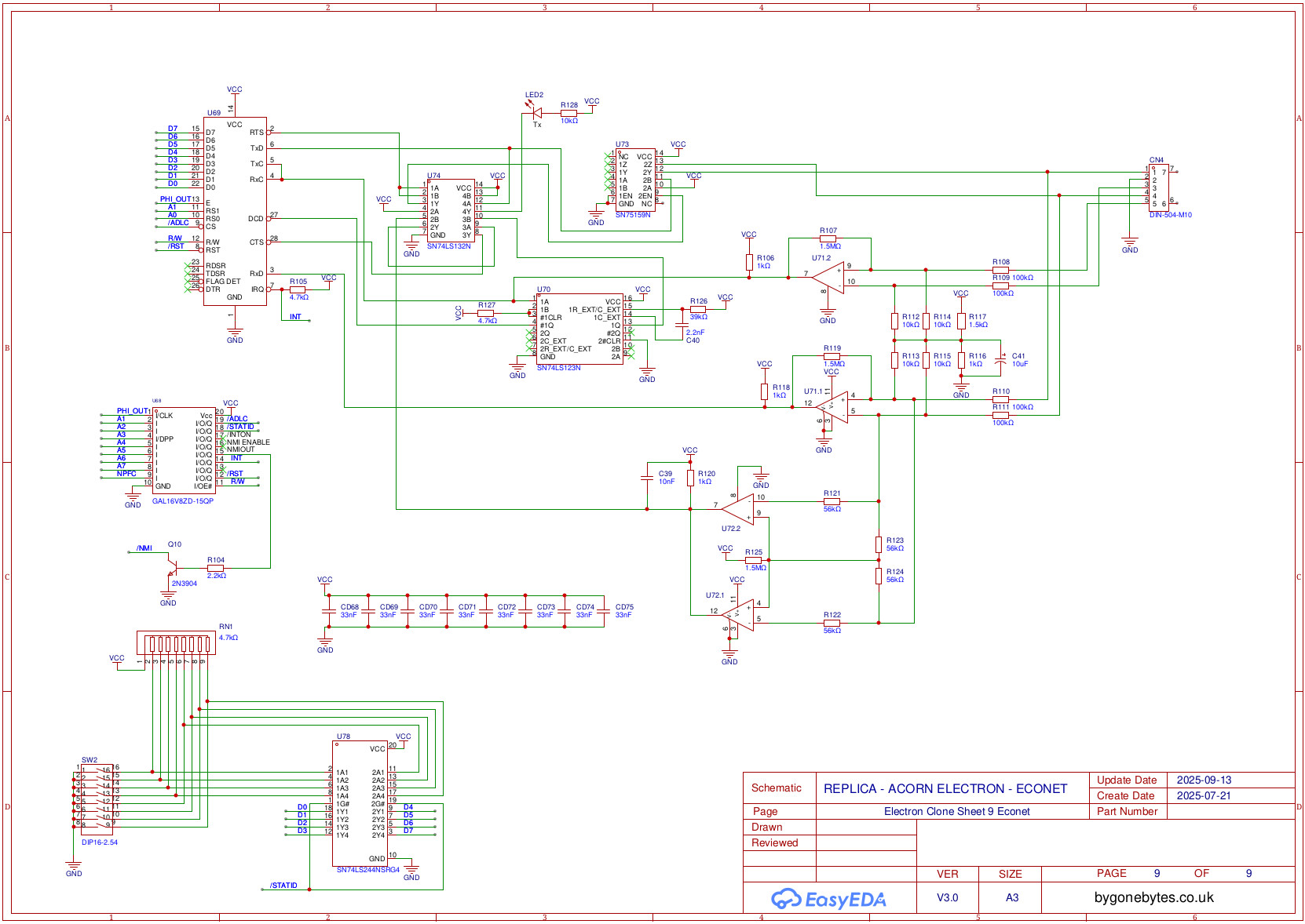
19/08/25 - The finalised circuit diagram and the board ordered - I decided to keep it black.
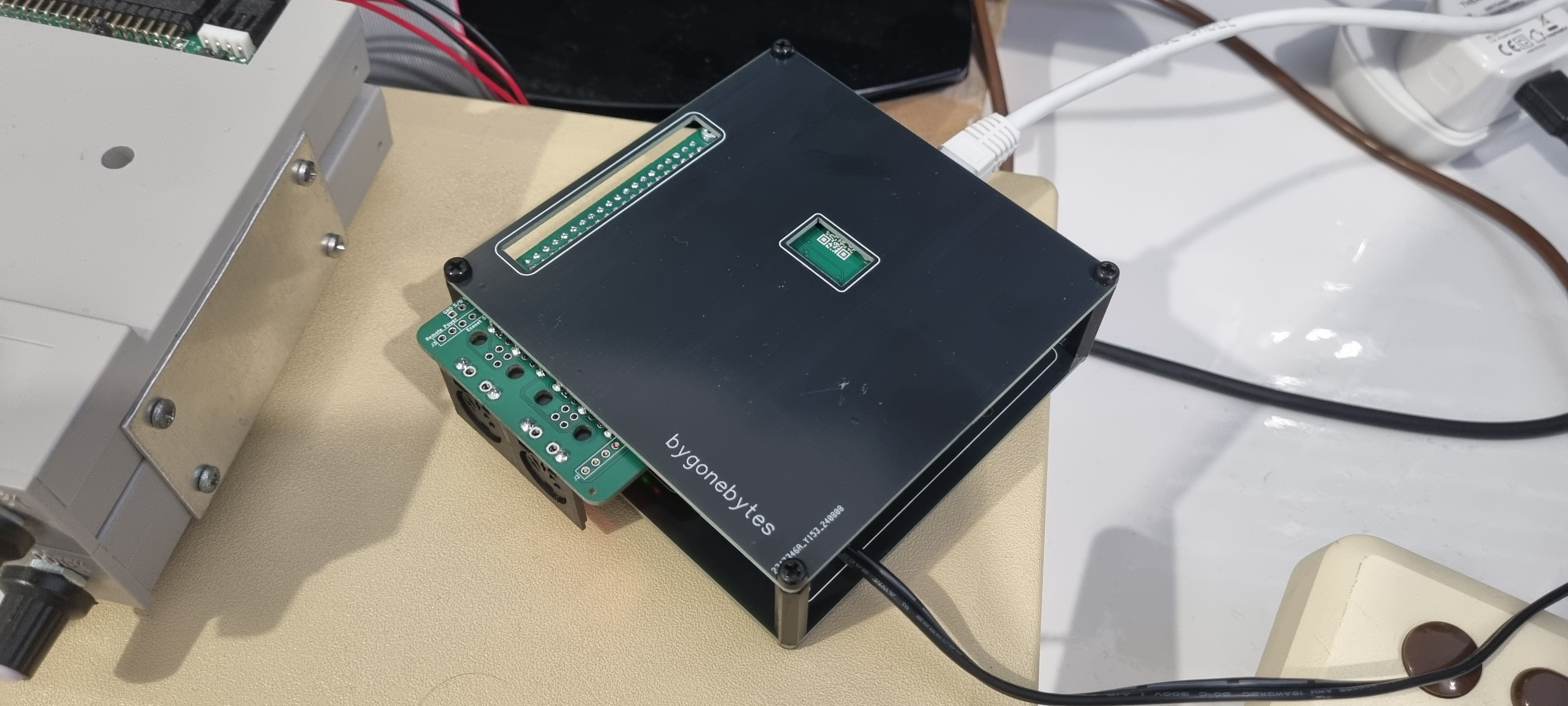
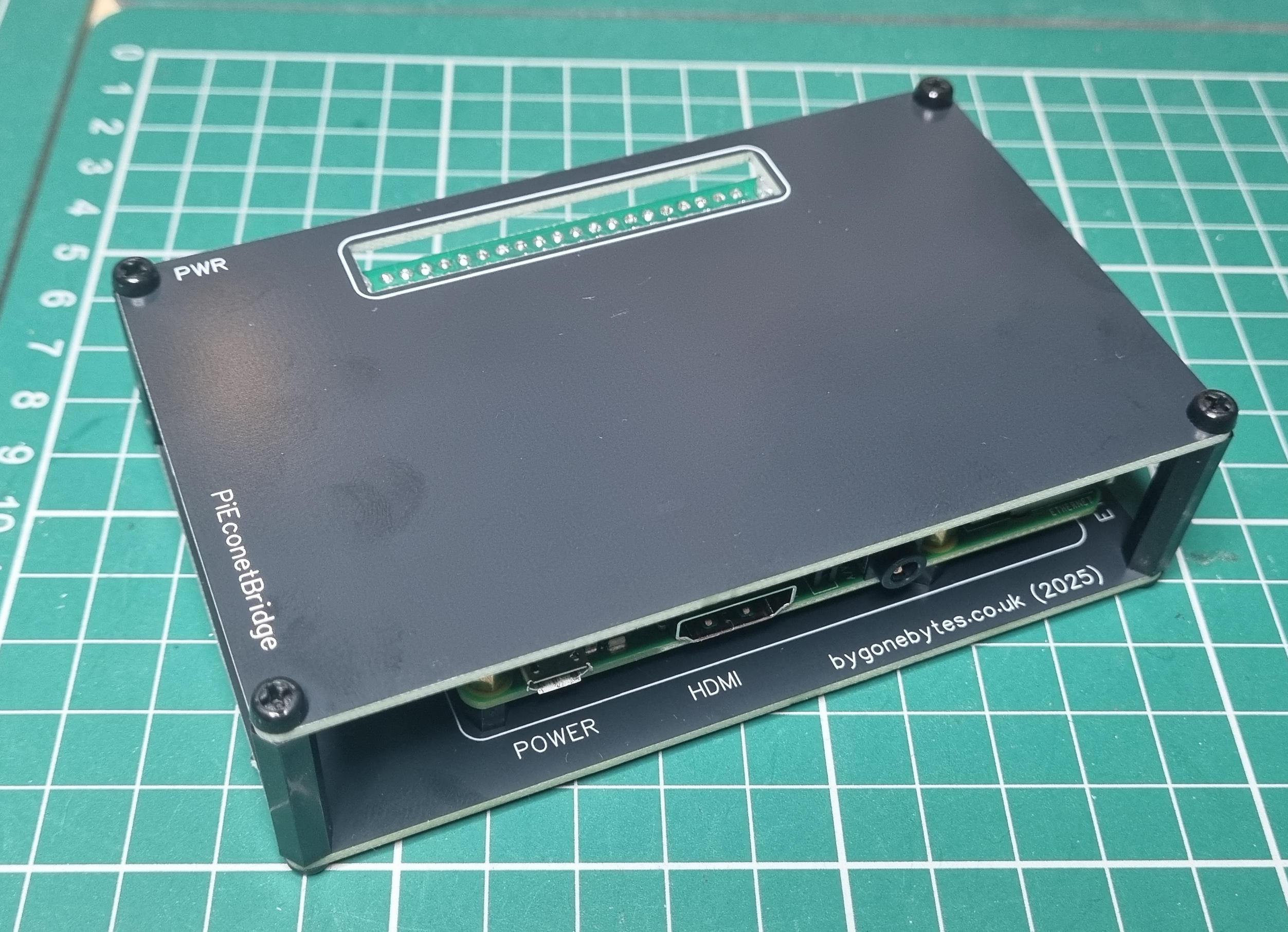
12/09/25 - Some PCB's have arrived. The first ones are the case for the PIEconetBridge. I designed the top and bottom to fit neatly over the Pi3 and the PiEconetBridge HAT and labelled each port.
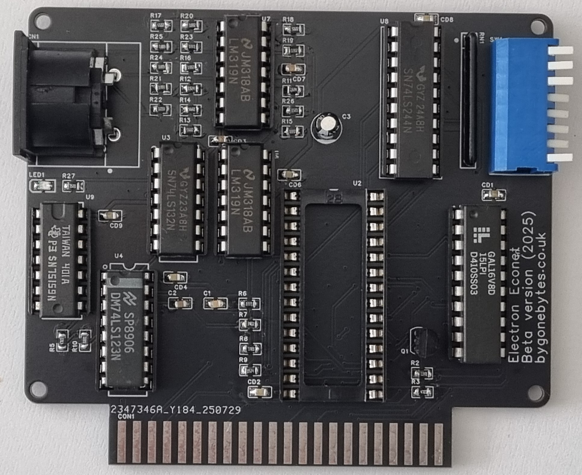
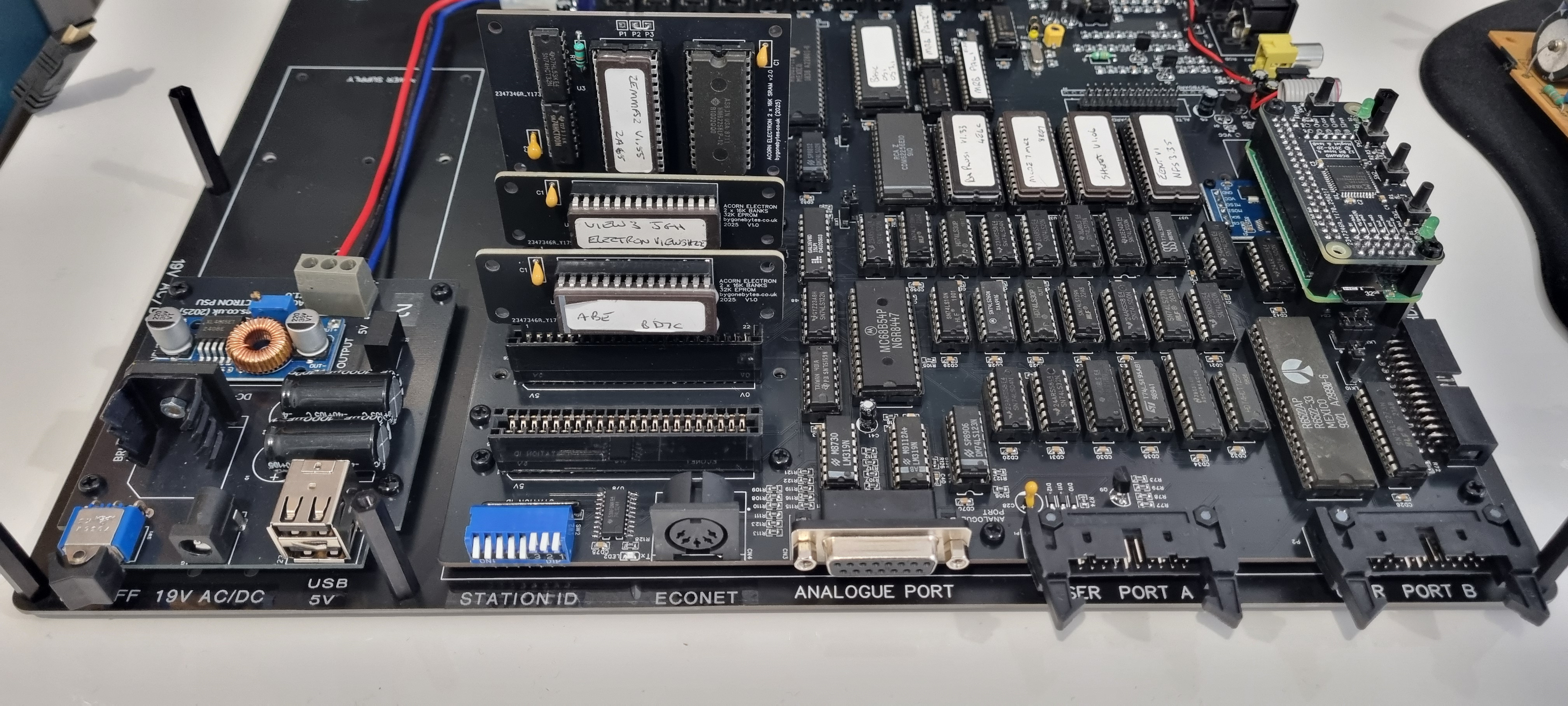
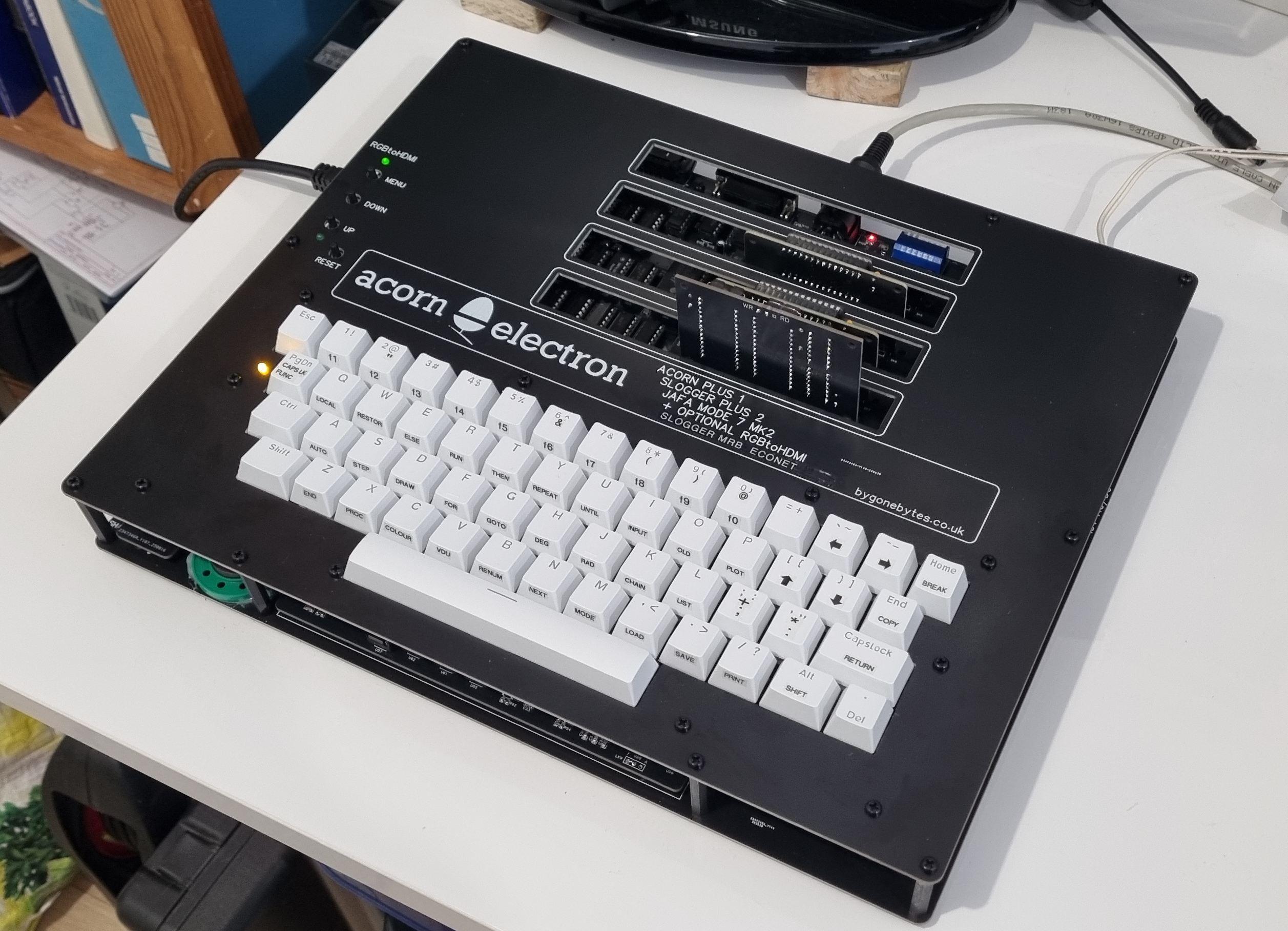
I have built up the version 3.0 PCB starting with the surface mount components then working up from the next tallest part until lastly the DIN connectors. Since I wasn't happy with the version 2.0 board I am going to transfer all the semiconductors from that on to V3.0 along with the Econet parts from the test board, this'll save me the usual messing around trying to find working parts such as the RAM etc. It took about a day and a half to assemble and is now ready for the transfer.
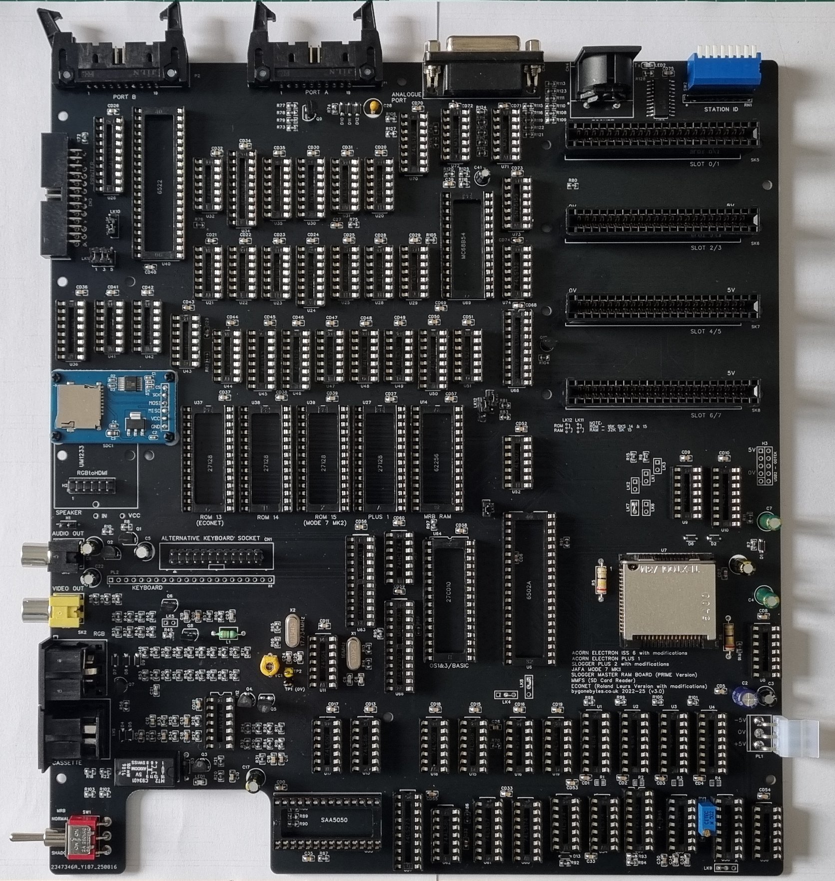
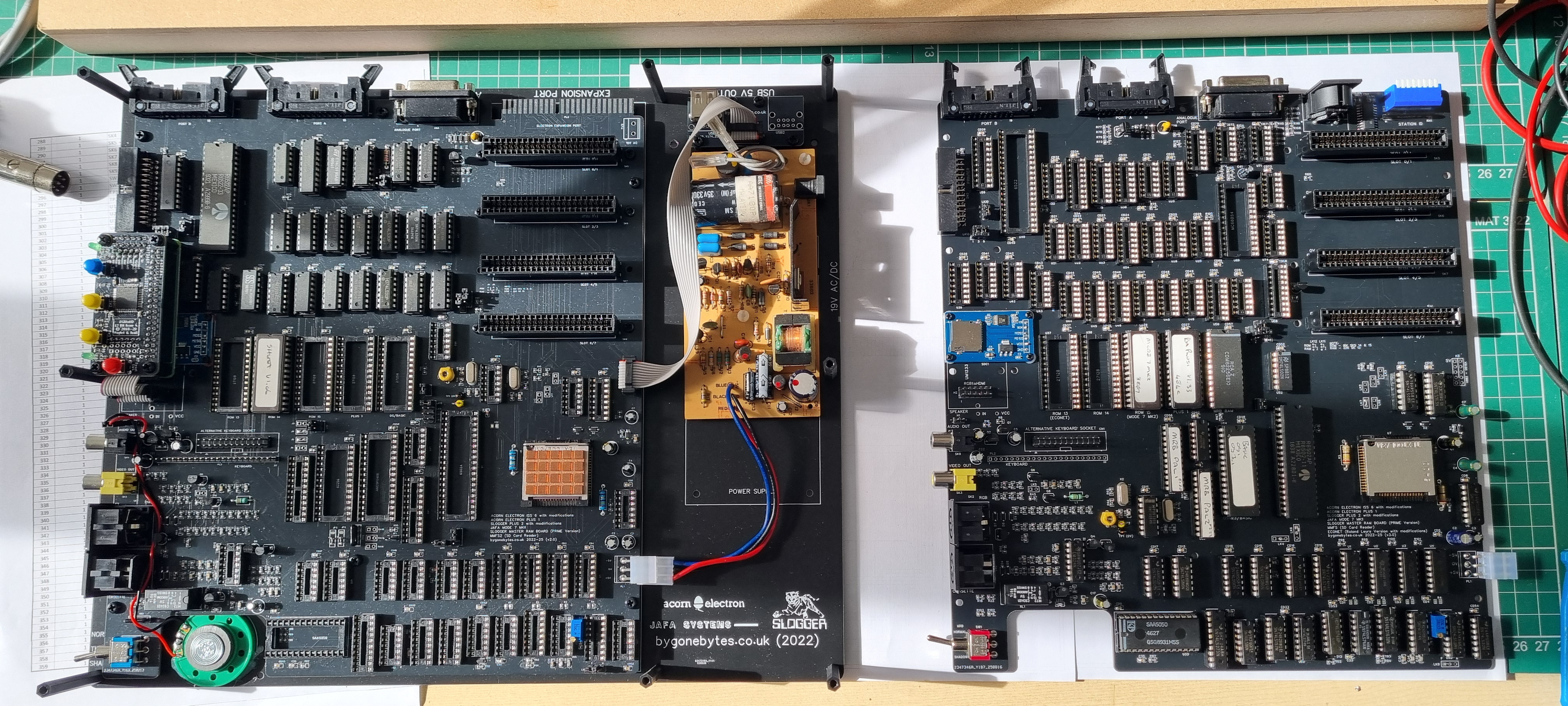
That's all the parts moved over from the donor board..just the Econet parts to move but I'll do that once I've checked the Electron is working ok.
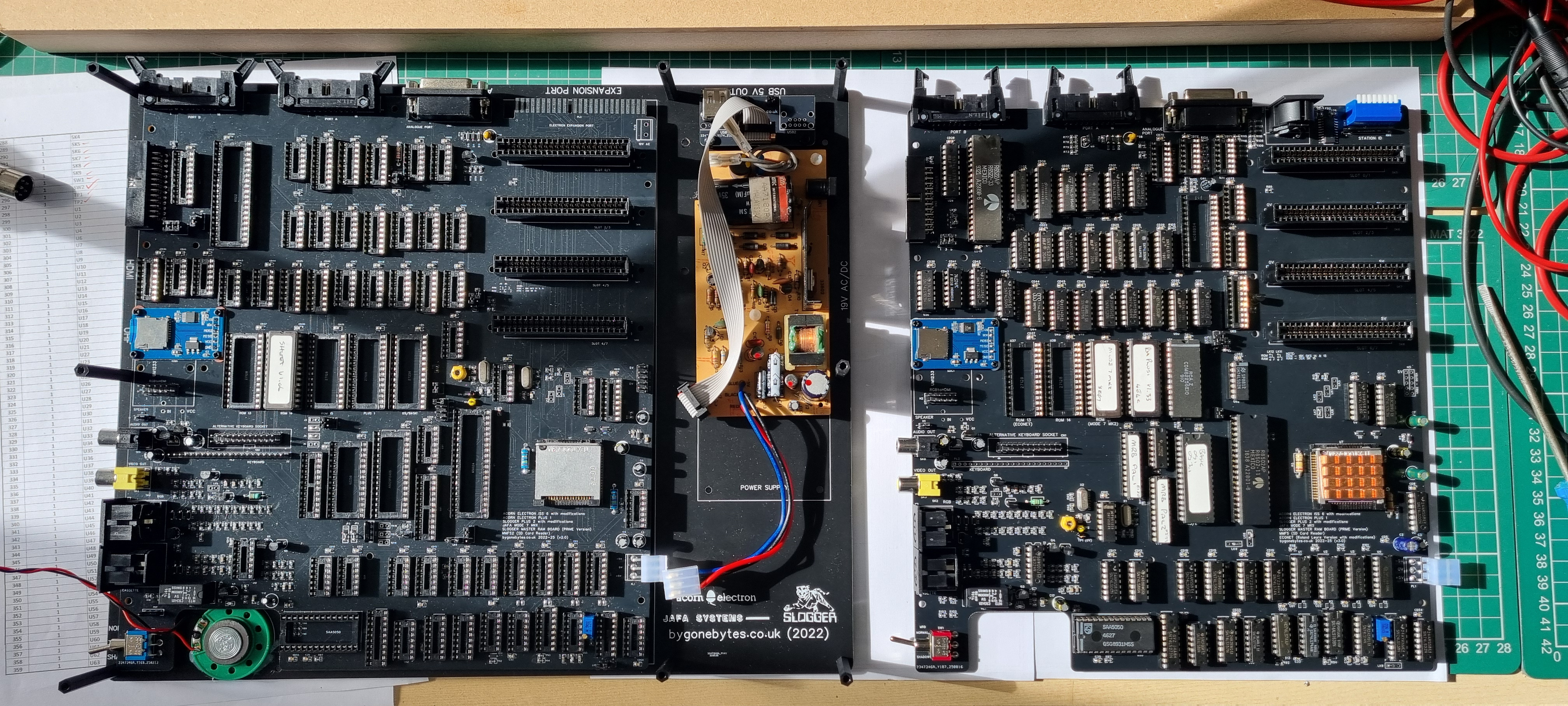
Everything worked ok first time! Time to move the Econet parts..
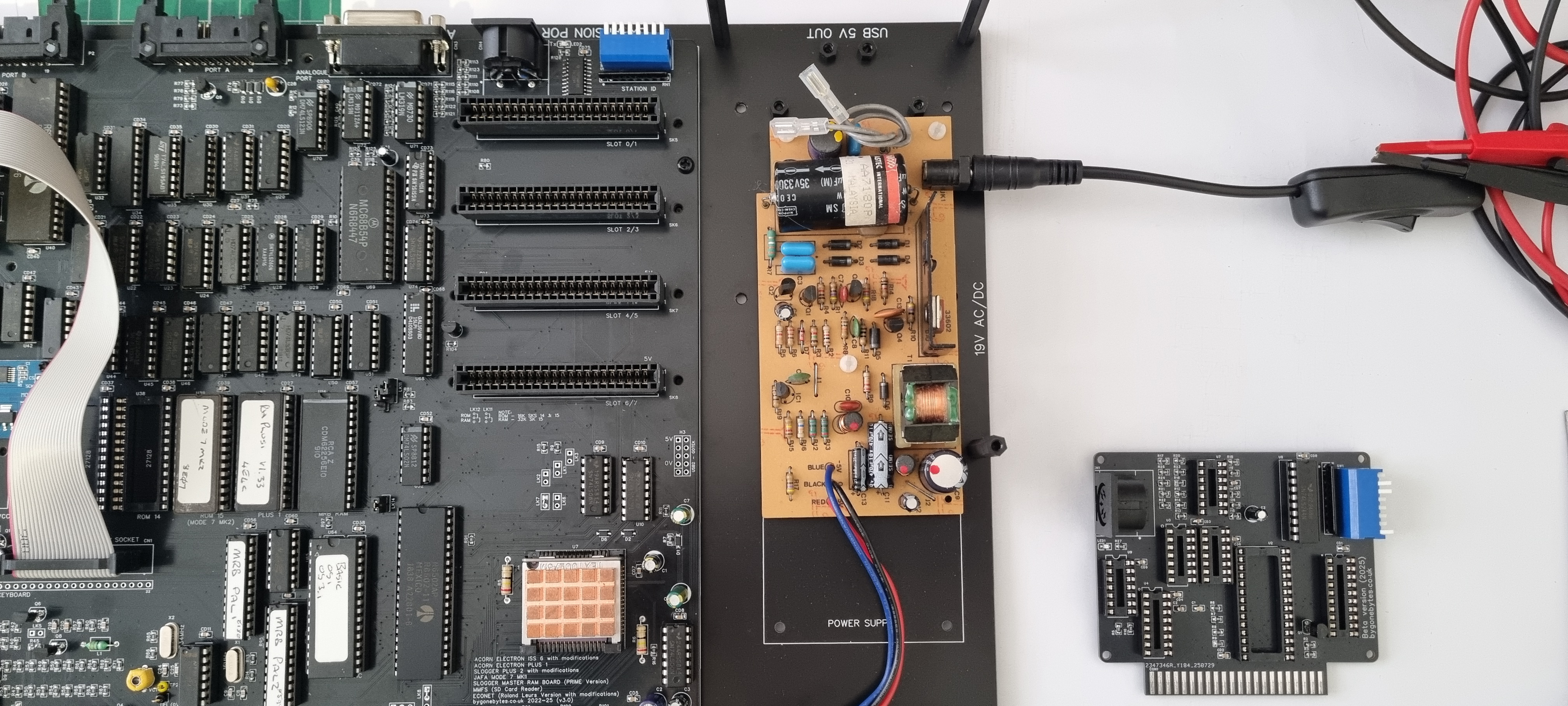
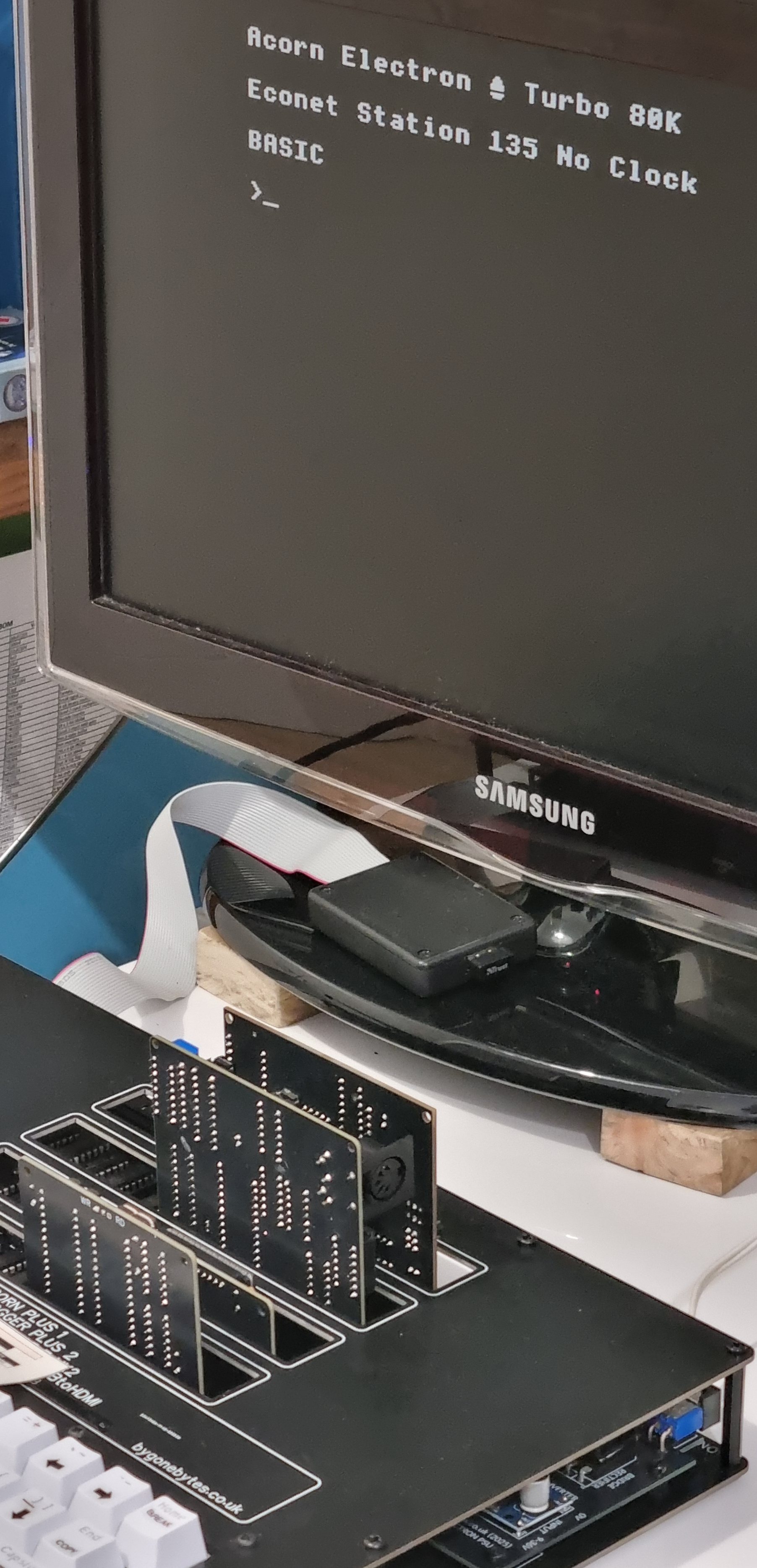
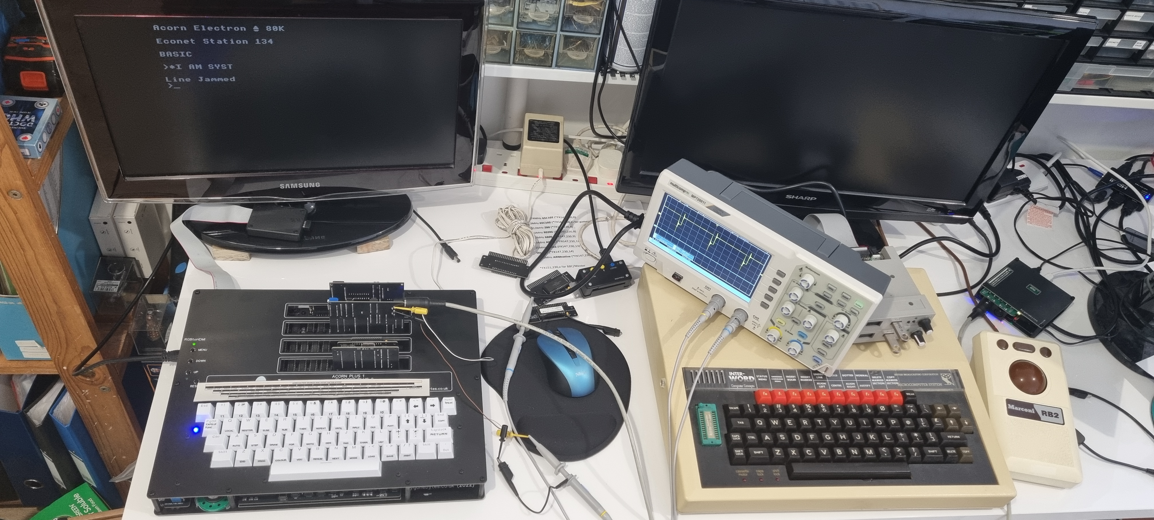
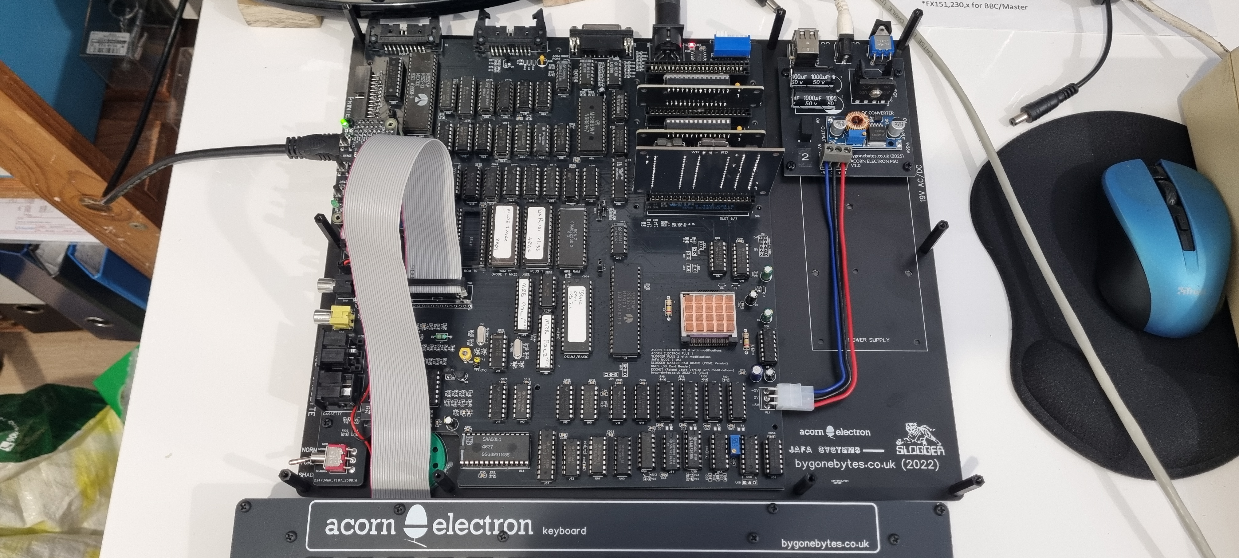
With that done I inserted the NFS ROM and checked it could read the Station ID ok. I then fitted the RGBtoHDMI and moved the Electron over to the desk with the PiEconetBridge, plugged in and success again, it was receiving the clock. Still lots to check - The User and Analogue Ports, MMFS and cartridge slots..
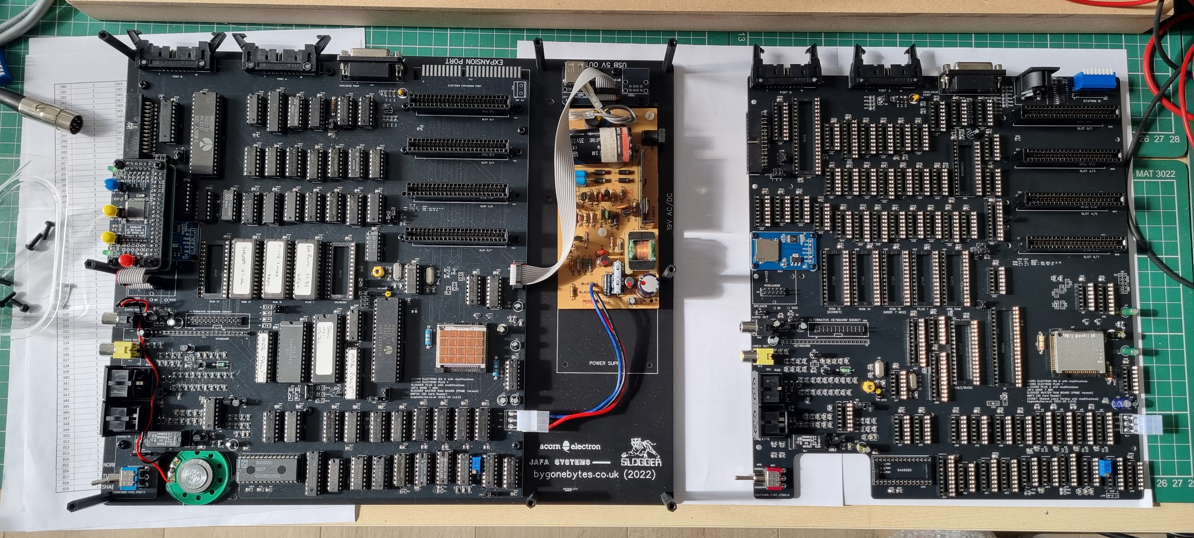
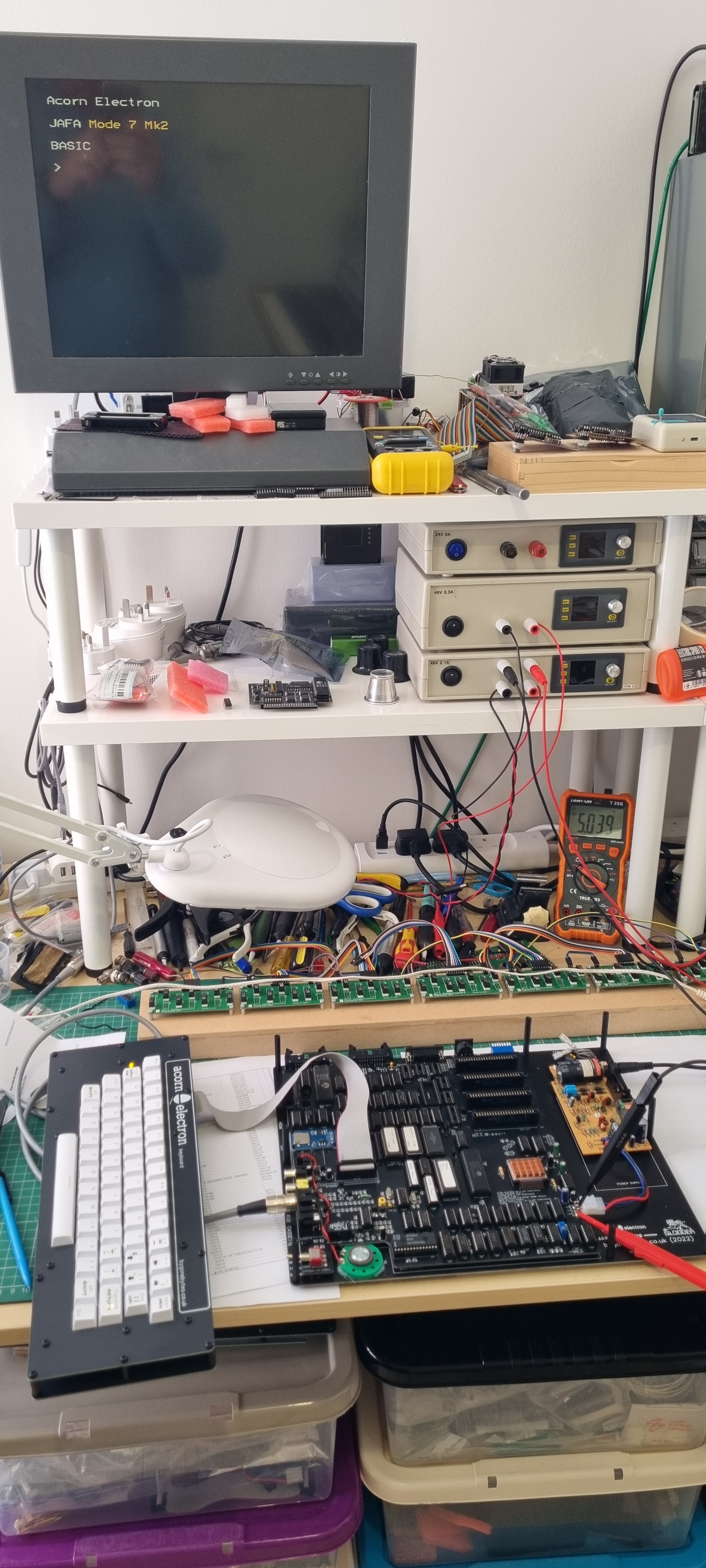
13/09/25 - Swapped the Electron PSU for one of my own so there is an On/Off switch and USB power socket.
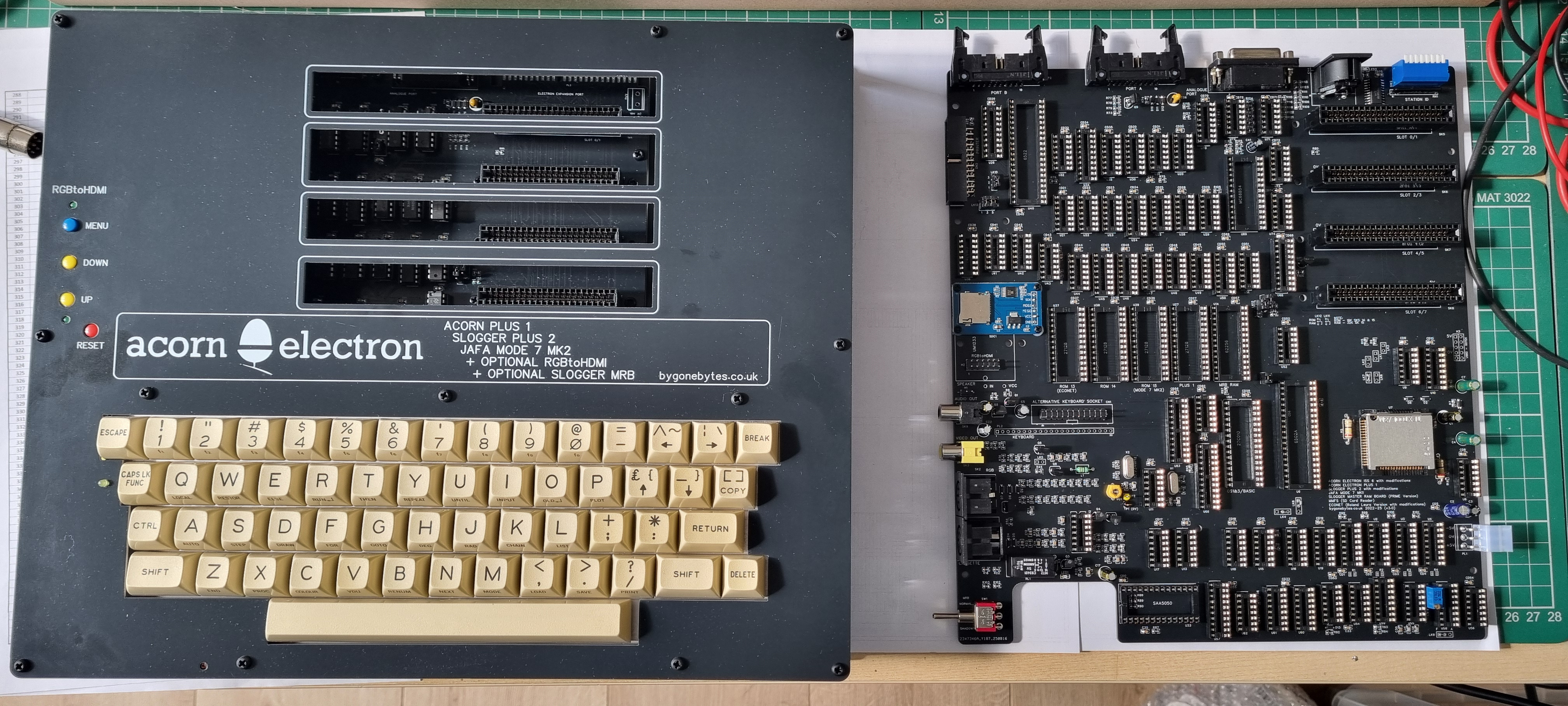
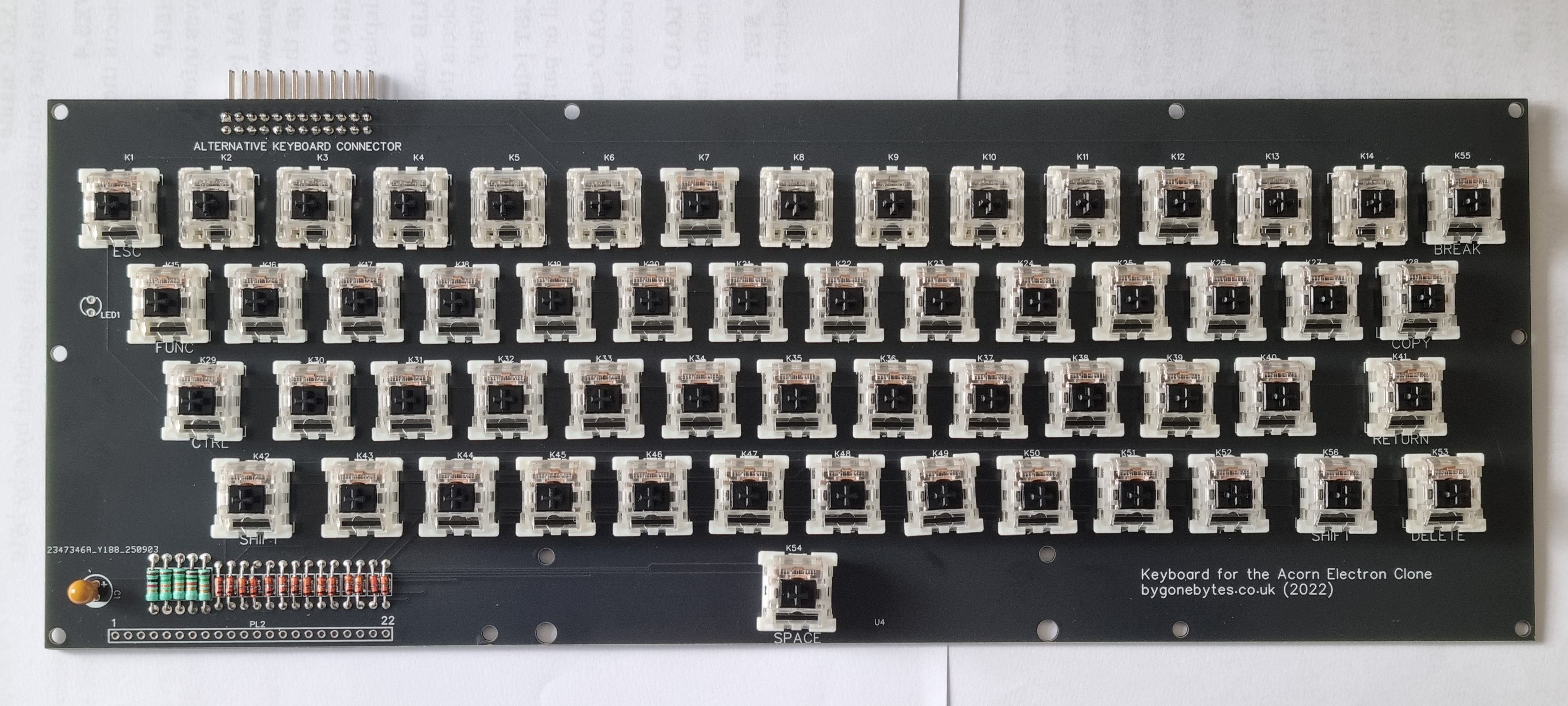
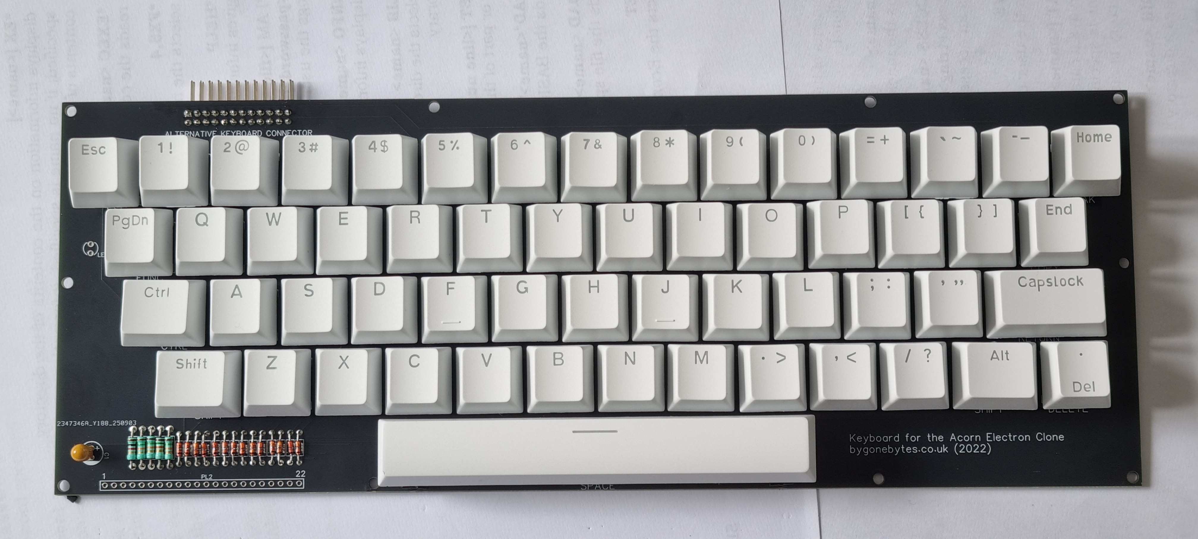
Built a new keyboard and updated the labels for the connectors.
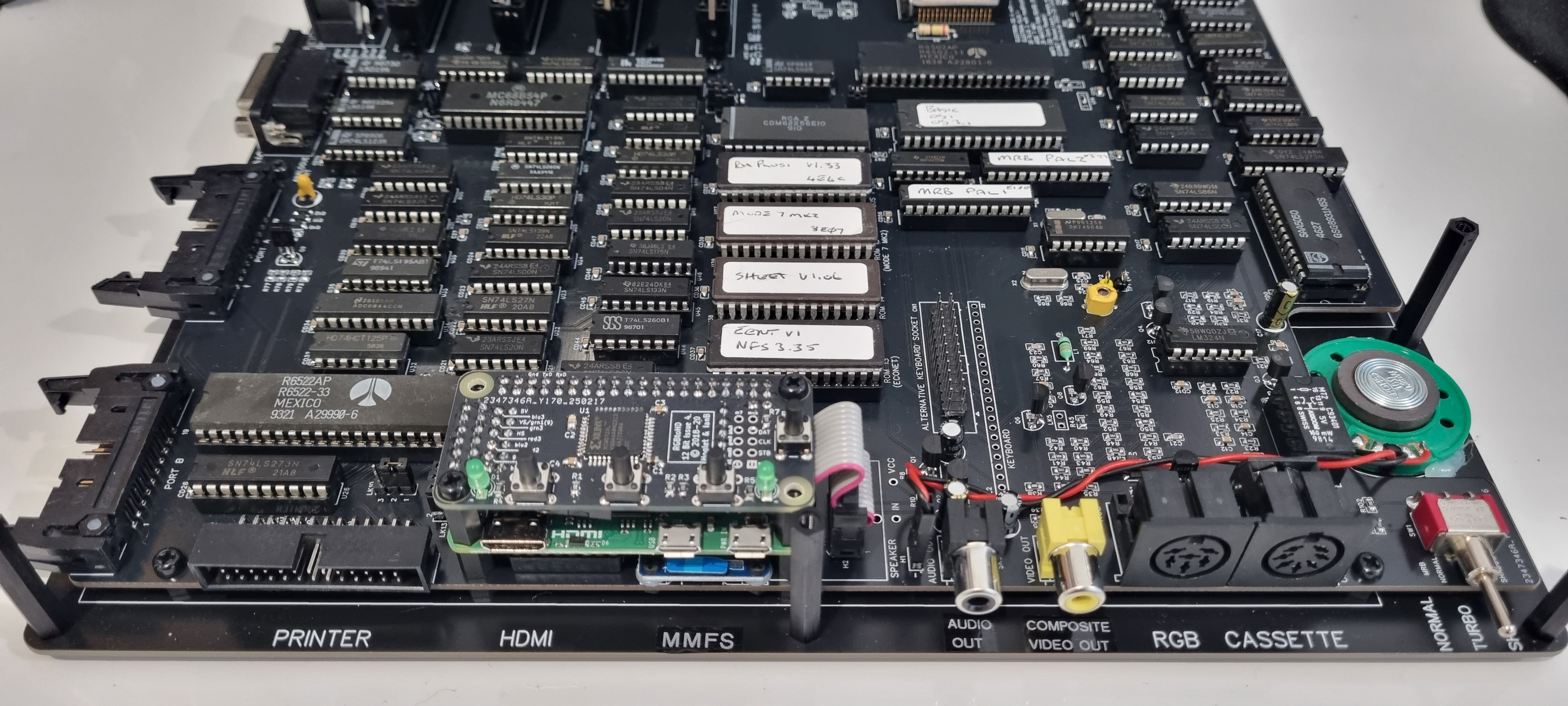
The finished Electron, it doesn't look any different from the previous version but it is now Econet enabled!
-END-