General Discussion
I have been thinking that the LCD screen would be a good alternative to the Cub monitor used with my Acorn Electron Sequencer. For this to work I will have to integrate the LCD display into a cartridge but there is limited scope to do this as both cartridge slots are in use.The current setup is:
Acorn Electron with Plus 1
E2p Second processor - 4Mhz with twin User Ports
Slogger Pegasus 400 Disc Interface
To achive this setup I already integrated the User Ports into the E2p so a re-think is required. The Plus 1 is needed as I use the analogue port for the tempo control so that rules out the Minus One - the Minus One would give me the extra cartridge slot but doesn't give me the flexibility of the analogue port!
So what is the best way to utilise the two cartridge Slots? At the moment I need the Disc Interface/Drive for storing and running the program leaving the other to hold the E2p and User Ports. I have finished working on the second processor and don't want to re-visit it to modify it again - it's running really well and I don't want to run the risk messing it up.
My thoughts have turned to integrating the User Ports, LCD Port and the Slogger Pegasus Disc interface into a single cartridge leaving the second slot for the second processor, this could either be the RPi/ATI combination or the E2p.
Using the 40x04 LCD display may have some advantages as the LCD does not carry the MODE(0) memory constraints thus I might not need a second processor and to regain the speed loss I could use a Turbo board instead.
If the second processor isn't required I should be able to fit the sequencer program into a ROM using the ROM filing system removing the need for the Disc Interface. Possibly at the end of the day I would only need a cartridge with User Ports, ROM sockets and the LCD Port - it all depends on speed and feel.
The use of a user port for the LCD means that the sequencer will be reduced from sixteen to eight trigger outputs, I considered using the printer port for the LCD but dismissed the idea as it would require a ribbon cable and from experience eight triggers is generally enough.
Getting started
The first stepping stone will be to integrate the Disc Interface, User Ports and LCD port into the one cartridge and using the RPi/ATI for testing the re-write of the sequencer program. Once built and programmed I'll be able to try out different Electron setups - basic, turbo and second processors. If turbo is responsive enough I'll make a cartridge with two ROM sockets, User Port(s) and LCD Port.
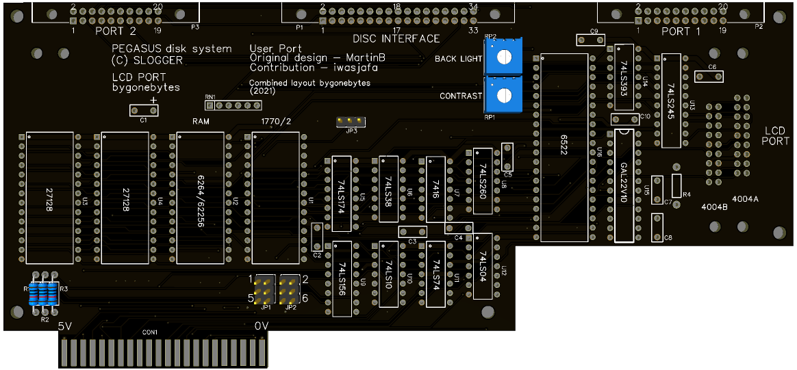
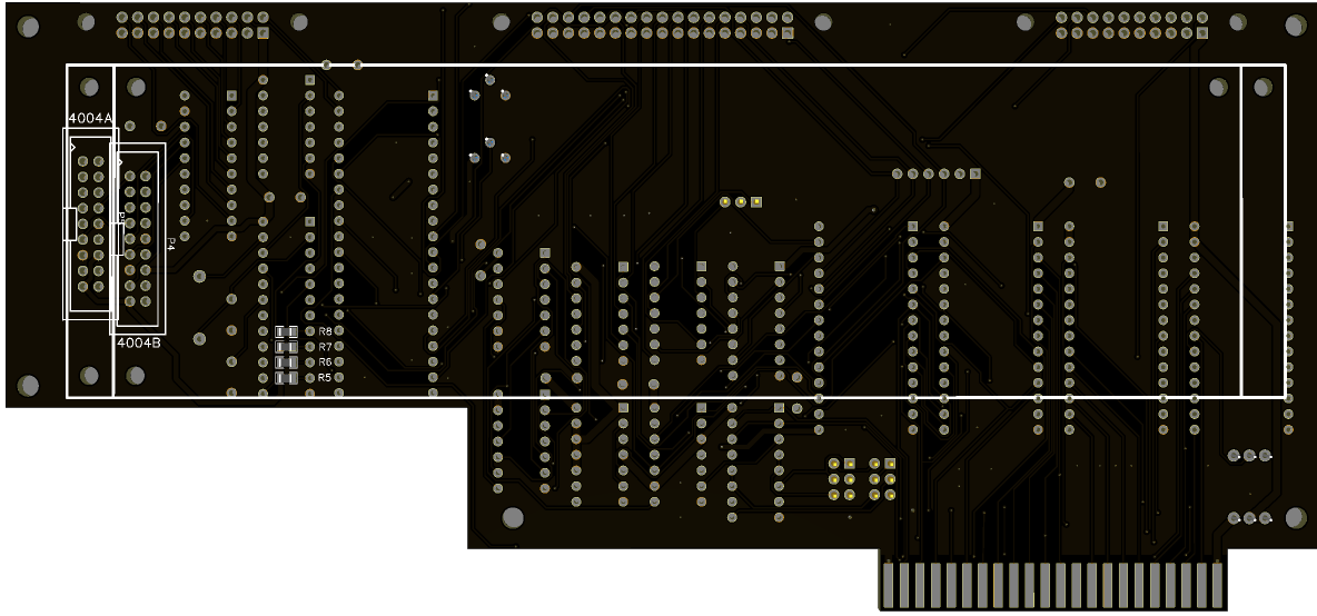
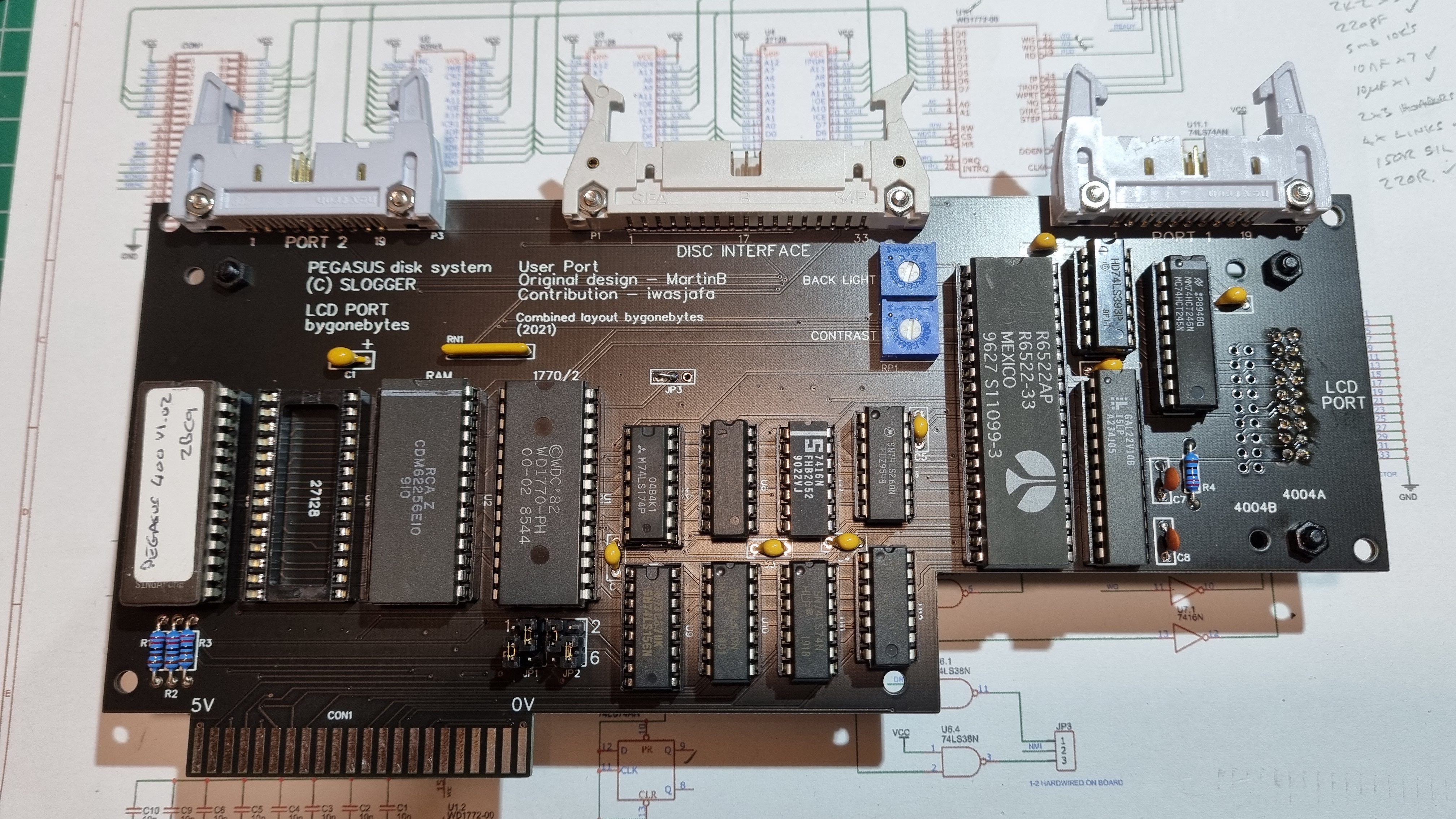
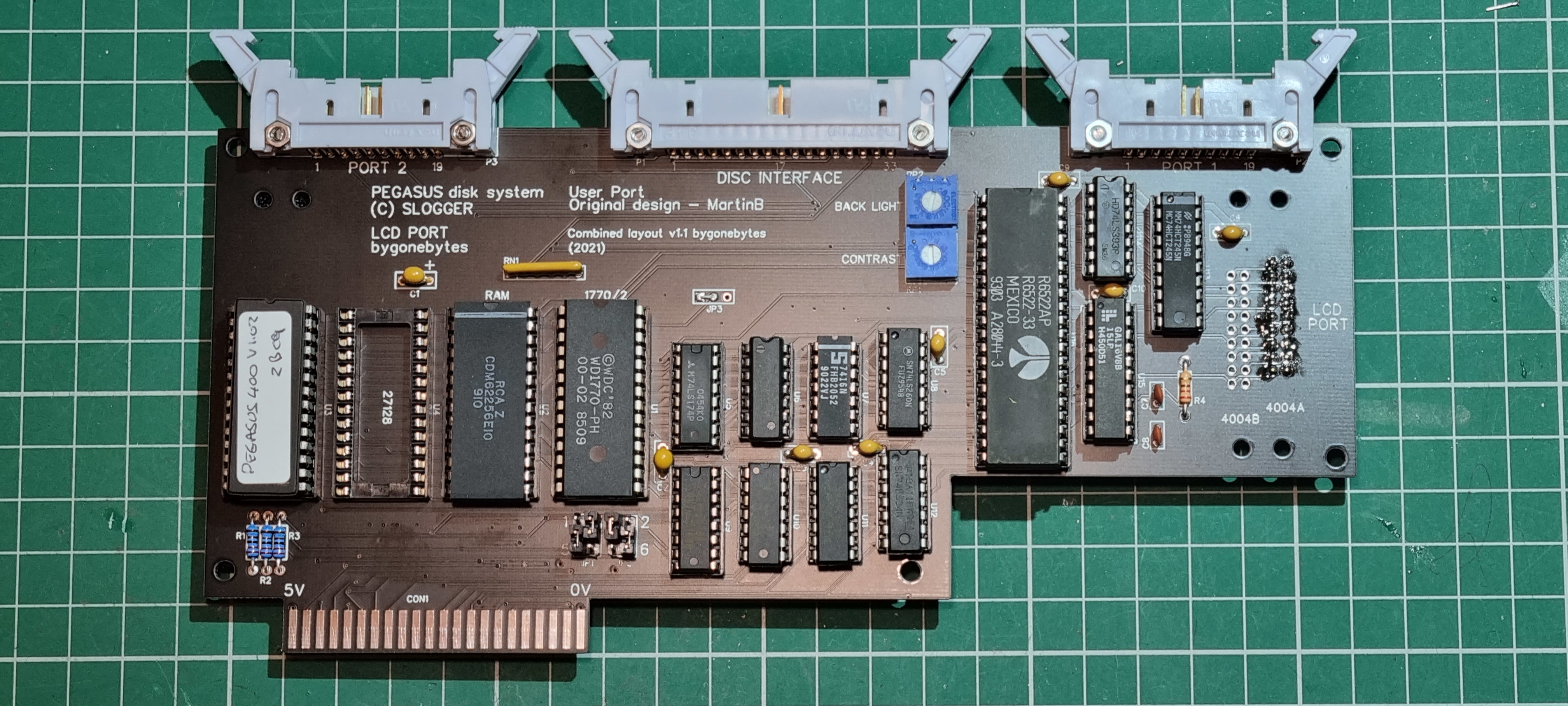
Front and Rear of new cartridge.
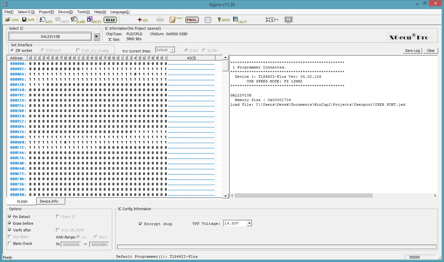
To keep the chip count and PCB size down I opted to use the GAL chip from the E2P for the User Port. This got me thinking about what is required to program such a chip and would it be simple enough for me to program it myself. These requirements are more or less staight forward, a programmer for the GAL chip and a programming environment for writing the equations. The programmer chosen was the TL866II Plus and the programming environment Wincupl.
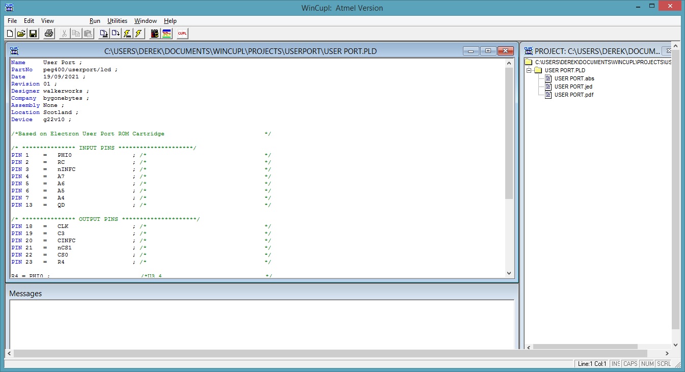
The good thing about this exercise is that I know the logic gates required from an earlier user port design and the I/O designations from the E2P so hopefully simplifying my first attempt at programming a GAL.
As a note I noticed that a GAL consumes approximately 90mA and that the four IC's it's replacing consumes roughly 10mA - nine times as much! so there is a trade off between space saved and power consumption on these small designs.
I have finished the Pegasus 400/UserPort/LCD Port build and it's all working well. I'm currently using the User Port GAL from the E2P which I may change once I've tested my own attempt at programming.
Programming the GAL turned out a bit tricker than I thought, I got caught out with the boolean implementation of the RS Flip-Flop but got there in the end. The User Port is now working with my own programmed GAL..
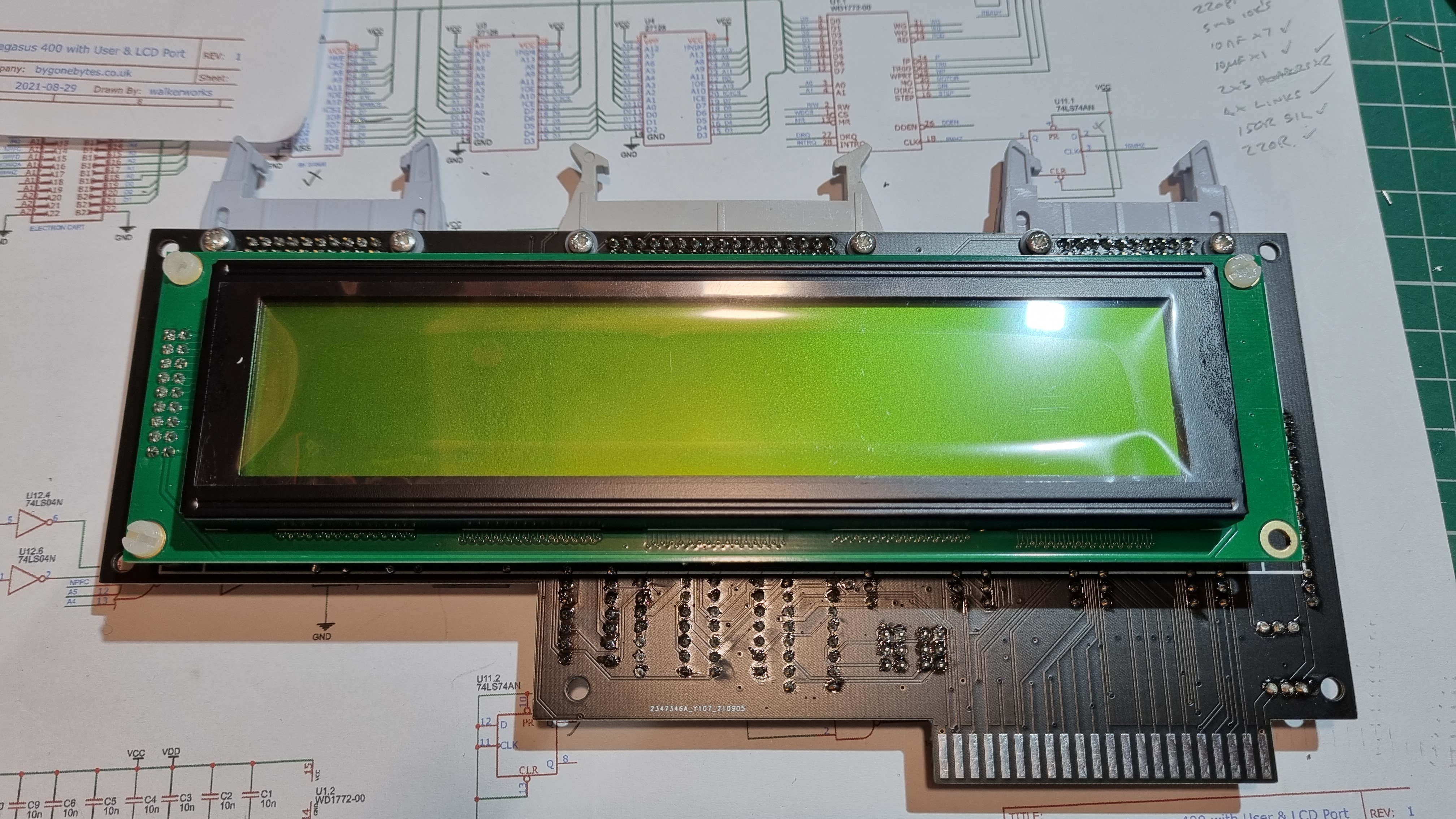
From my research there are two common 4004 displays, the 4004A and the 4004B. Functionally they are the same but the connector pinouts are different, two major differences are the data pins are reversed and the connector for the 4004A is 18 Pin and the 4004B 16 Pin + 2. I made allowances for both on the circuit board and used the 4004A display, the protype was a 4004B.
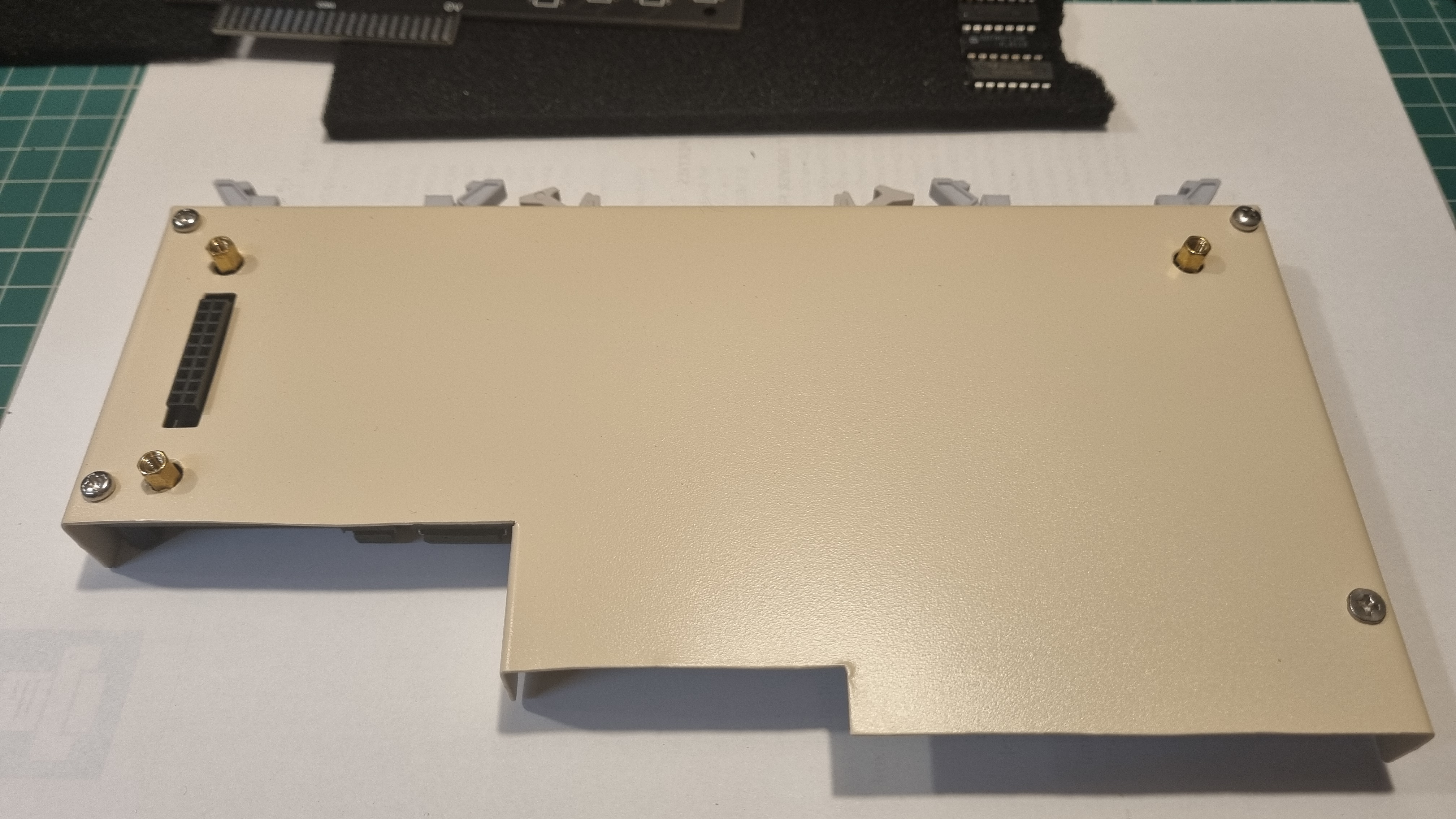
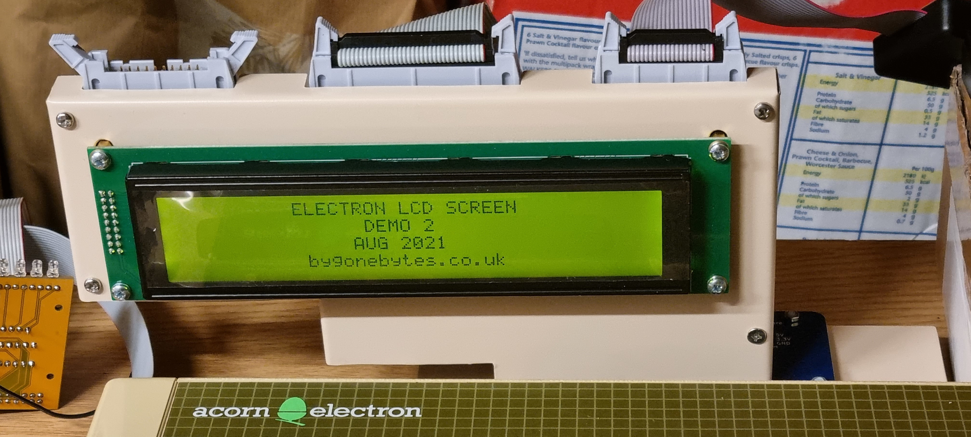
The complete cartridge is quite heavy so I'll make a case to support and protect it. The video below shows my earlier demo program running on the new cartridge. It's plugged into a Minus 1 but it is destined to be used in a Plus 1.
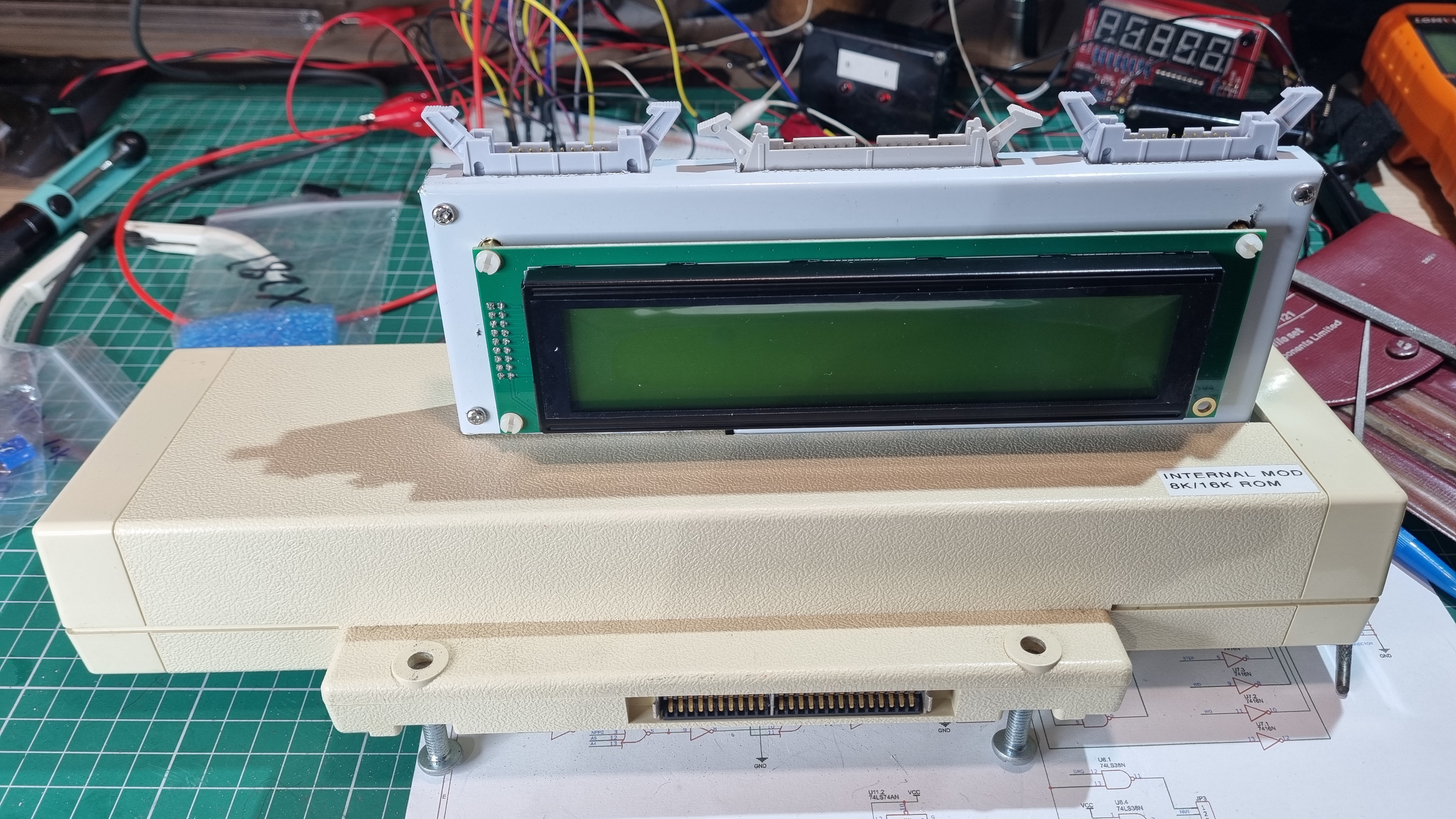

Aluminium folded, drilled and test fitting in the Plus 1. Case painted and the fitting of the PCB.
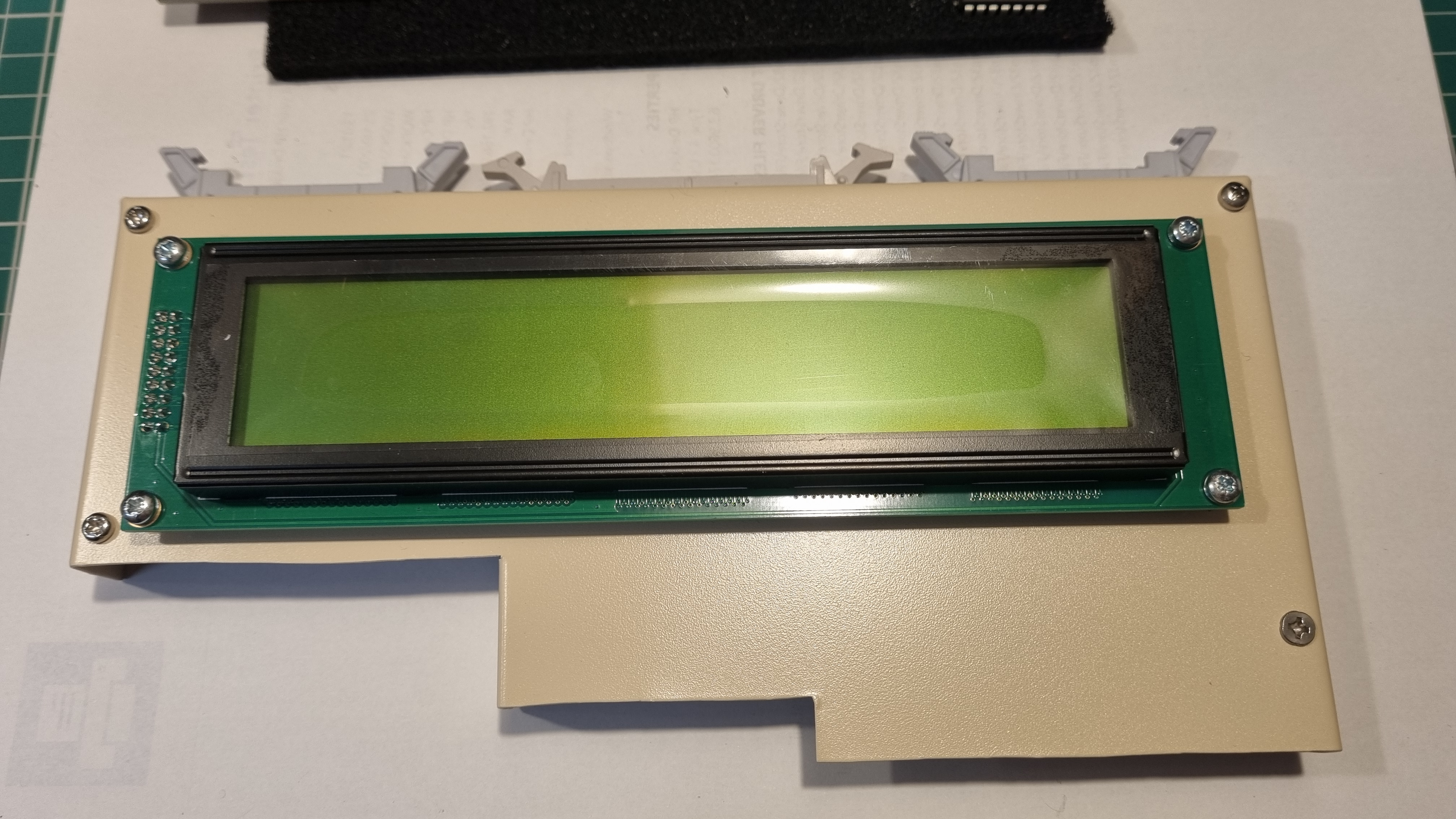
Mounting the display is simply a push fit and a few bolts to support it.

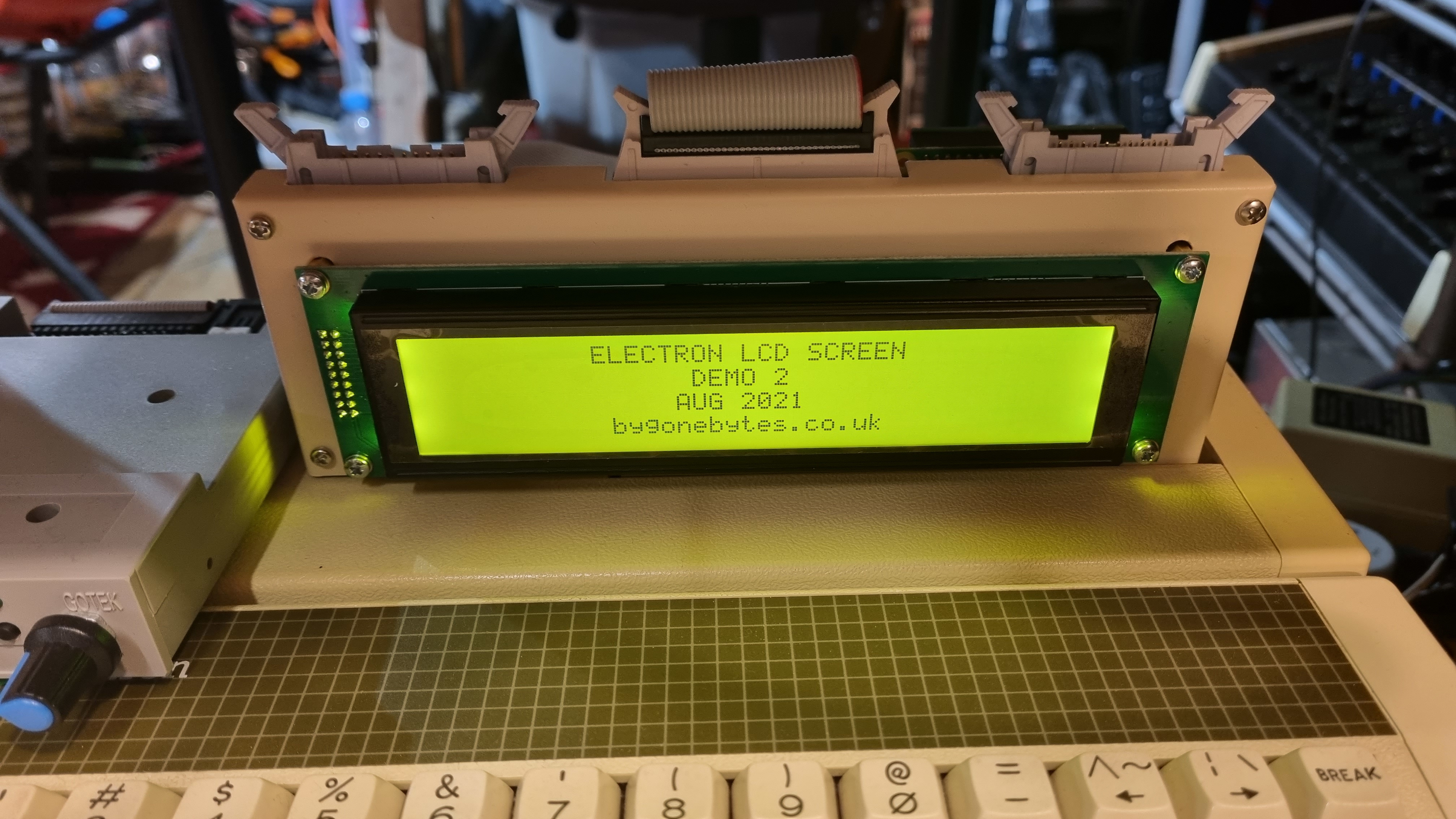
Installed and running on the Electron. Behind the new cartridge is an ATI with Raspberry PI Co-processor.
*UPDATE*
With my findings that the ROM/User Port cartridge wasn't working with a mouse I have re-worked this board to add the circuit and GAL program changes I made to the ROM/User Port Cartridge. I also took the opportunity to reduce the size of the GAL by using a 16V8 instead of the 22V10. The 22V10 was only used on this board as I was originally using the 512KE2P User Port jed file.
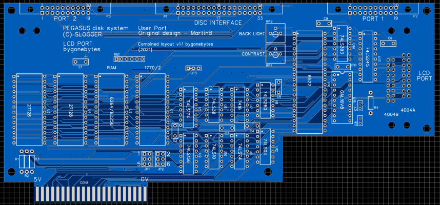
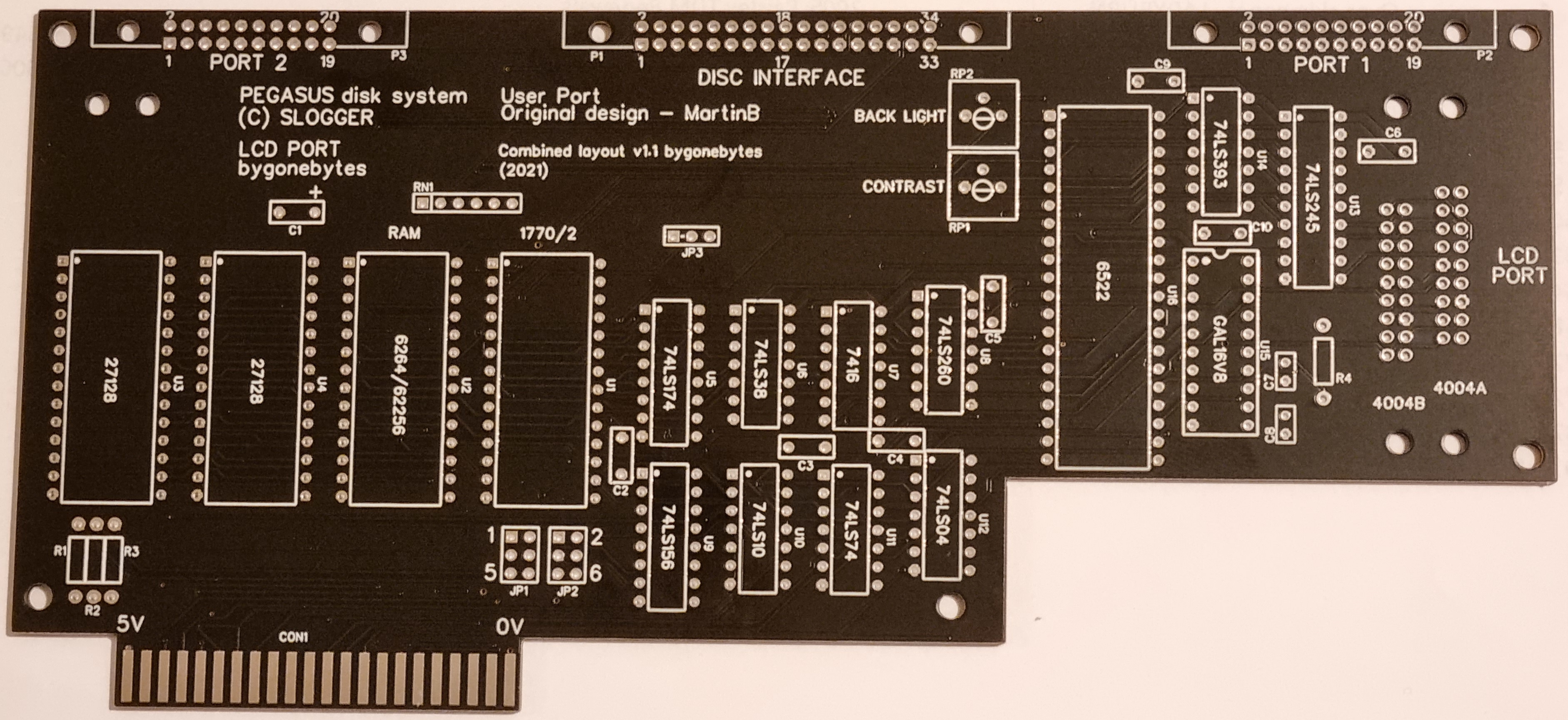
PCB Revision 1.1
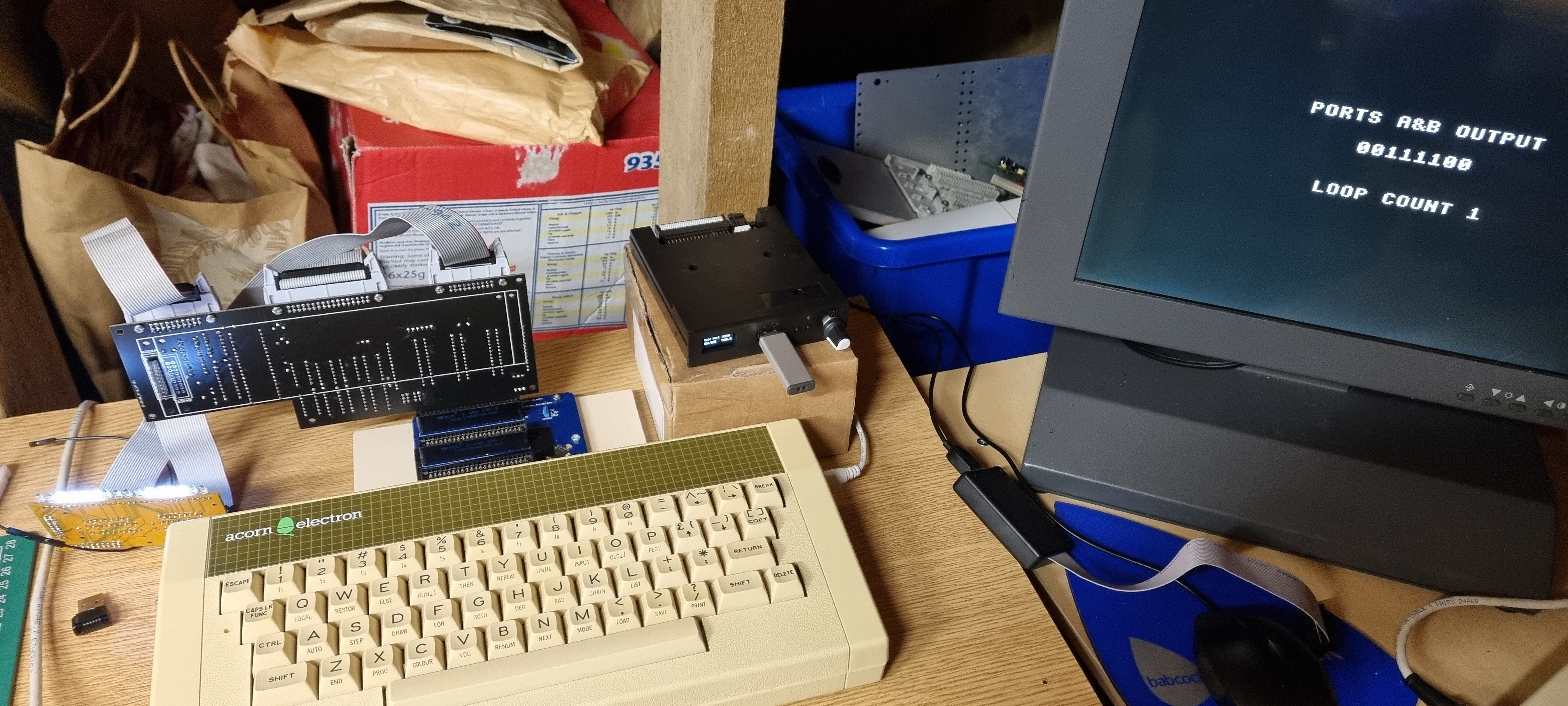
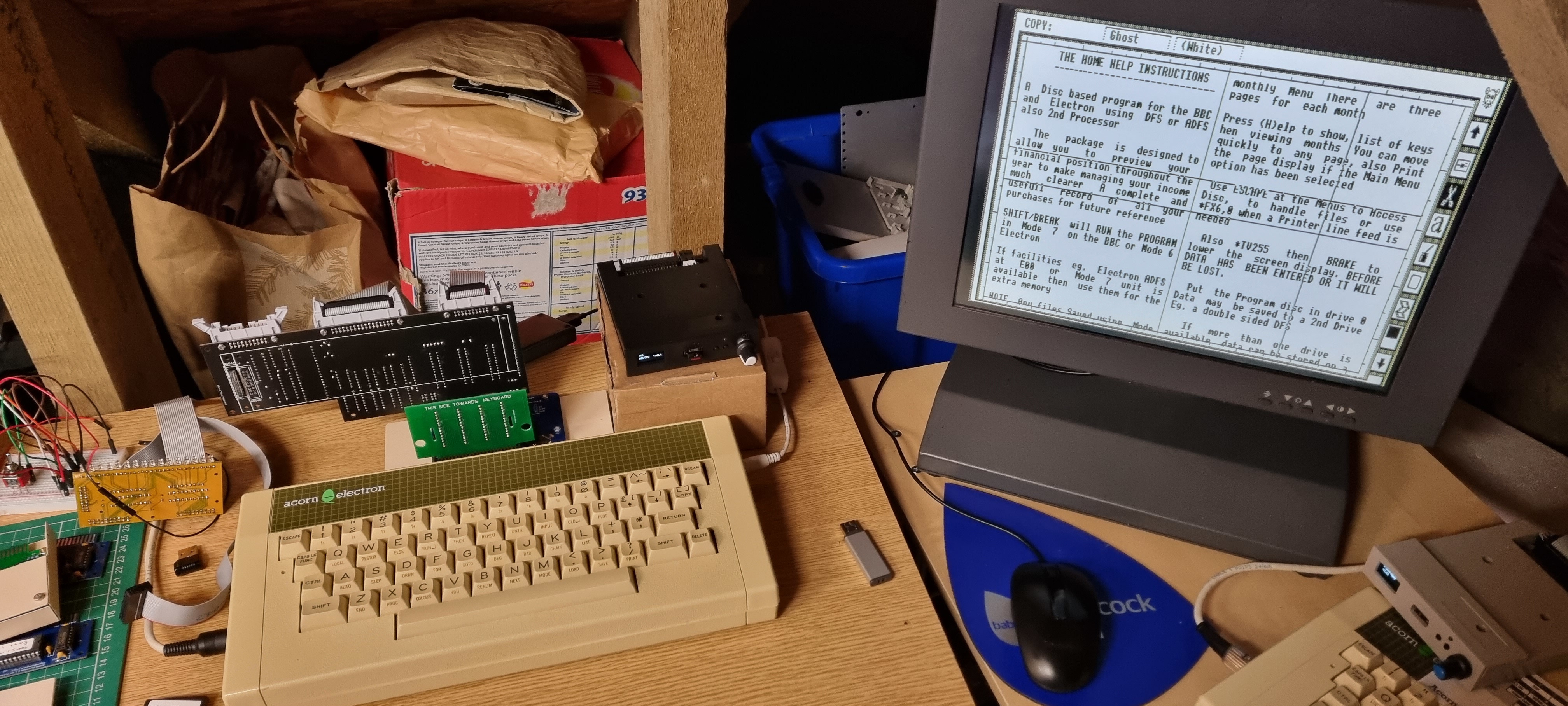
Building the new PCB, testing the ports, testing Port 2 with Stop Press and mouse and assembled into its case for Screen Testing.
Finally testing the mouse to ensure it didn't interfere with the screen.
*The Screen*
Whilst the two screen types have essentially the same protocols I found that the response times between certain commands on the 4004A are a bit slower so I had to make an ajustment to the delay timing. I have done this and added the file LCDRPI3 to the zipped disc image on the 40x04 LCD page.