20 column x 4 row LCD Screen for the Acorn Electron
I recently used a 2004 LCD screen on a couple of RPi Pico projects and it got me wondering whether I could build this screen onto the Electron User Port. For the Pico I used an I2C interface with libraries to simplify the programming of the LCD. The basic display uses an eight bit bus with three control lines, W/R, Enable and Instruction/Data which I think will make it possible to use with the Electron.The Acorn Electron User Port has eight data lines, not enough to control the display as when you take into account the control lines I'd need eleven. There are two different approaches I could take, the first is to use two User Ports, one Port for the data and the second for the control lines - this would be the simplest method to program as it would be fairly simple transfer the ascii characters to the display. The second option is to use the four bit interface function available in the display - this looks a bit trickier to implement but only one User Port would be needed. The top four bits for data clocked twice (sounds familiar to Electron users!) leaving the bottom four bits available for the control lines.
With both options in mind I designed a simple buffered interface PCB with some LED's and to support the LCD screen. For this prototype it'll plug directly into one User Port connector and if a second port is needed it can be accessed via a ribbon cable connection.
My intention is to try and use the 4 bit/single User Port option to keep the hardware as simple as possible but I realise it'll makes the software a bit more cumbersome. My aim is to write some PROCedures that will make it easy to pass instructions or data to the display such as switching the display on/off, switching the cursor on/off/blink, move the cursor to a desired position and to send the text. So here goes..
Part 2 - building the interface.
The Interface:
I've selected this low cost 20 column x 4 row white LCD display module to base the project on and designed a simple one direction interface with a few options to allow me to try both the 4 bit and 8 bit data bus options to send information to the screen. Other additions included LED's on the data bus so I can see at a glance the state of the bus and an option for internal or external power for the board. For the components I opted to use surface mount parts, I normally use through hole parts but with the little experience I've gained with building the Minus One and the Electron OSTC I thought it would be good design for me to start with.

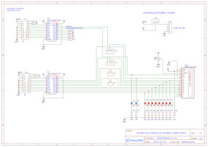
Display Module and interface circuit.
The PCB:


Component and display sides of the PCB.
Assembling PCB:


All the parts required to assemble the board, I started with the tiny LED's.


Then the resistors and buffer IC, 74HCT245 and the USB power connector. I thought I'd have trouble soldering the connector directly on the PCB so I opted for one already on a small daughter board.

Next the jumpers, header and contrast potentiometer.


Finally mounting the display on the board.


I tested the PCB prior to fitting the display then tested it again with the display attached. The total current drawn is 37mA so I should be able to power it directly from the Electron.
Part 3 - building a test program
To build a test program I re-used the assembly routines from the sequencer program trimmed down for a single port and adding PROCedures and SUB routines to define the protcol for some instructions and data transfer. Instructions to control the display include: Clear Screen, Cursor Blink, Cursor On, Cursor Off, Cursor Left, Cursor Right and Cursor Home.
I've left a fair bit of redundant code in the program by using REM or \ to comment out what isn't needed at the moment.
10REM bygonebytes.co.uk (2021) LCD V0.01
20REM IF HIMEM <&8000 THEN 30 ELSE 50
30REM PRINT"Switch on your Electron 2nd processor"
40REM END
41IF HIMEM>&7C00 THEN HIMEM=&8000
50MODE3
55VDU19,0,4;0;0
60HIMEM=HIMEM-2
61A%=HIMEM+1
80DIM Q% 100
90P%=Q%
100[OPT 0
110.init LDA #&93
120LDX #&B3
130LDY #&FF
140JSR &FFF4
150\LDA #&93
160\LDX #&B2
170\LDY #&FF
180\JSR &FFF4
190RTS
200.write LDY A%
210LDA #&93
220LDX #&B1
230JSR &FFF4
240\LDY A%
250\LDA #&93
260\LDX #&B0
270\JSR &FFF4
280RTS
290.zero LDY #&0
300LDA #&93
310LDX #&B1
320JSR &FFF4
330\LDY #&0
340\LDA #&93
350\LDX #&B0
360\JSR &FFF4
370RTS
380]
390CALLinit:CALLzero
400PROCinitdisplay
410PROCkey
520END
530DEFPROCinitdisplay
540PRINT "INITIALISING DISPLAY"
670?A%=&20:CALLwrite
680?A%=&21:CALLwrite
690?A%=&20:CALLwrite
700PRINT"4 BIT MODE SET"
710?A%=&21:CALLwrite
720?A%=&20:CALLwrite
730?A%=&80:CALLwrite
740?A%=&81:CALLwrite
750?A%=&80:CALLwrite
760PRINT"4 BIT MODE SET / 4 LINES"
770?A%=&00:CALLwrite
780?A%=&01:CALLwrite
790?A%=&00:CALLwrite
800?A%=&C0:CALLwrite
810?A%=&C1:CALLwrite
820?A%=&C0:CALLwrite
830PRINT"DISPLAY ON"
840?A%=&00:CALLwrite
850?A%=&01:CALLwrite
860?A%=&00:CALLwrite
870?A%=&10:CALLwrite
880?A%=&11:CALLwrite
890?A%=&10:CALLwrite
900PRINT"DISPLAY CLEAR"
910?A%=&01:CALLwrite
920?A%=&00:CALLwrite
930?A%=&60:CALLwrite
940?A%=&61:CALLwrite
950?A%=&60:CALLwrite
960?A%=&00:CALLwrite
970PRINT"CURSOR HIDDEN"
980ENDPROC
990DEFPROCkey
1000A=GET
1020ON (A-47) GOSUB 1650,1170,1330,1250,1410,1490,1570 ELSE 1040
1040ON (A-64) GOSUB 1070,1730,1810,1890 ELSE 1000
1050GOTO 1000
1070REM senda
1080?A%=&42:CALLwrite
1090?A%=&43:CALLwrite
1100?A%=&42:CALLwrite
1110?A%=&12:CALLwrite
1120?A%=&13:CALLwrite
1130?A%=&12:CALLwrite
1140?A%=&00:CALLwrite
1150PRINT"A"
1160RETURN
1170REM clear
1180?A%=&00:CALLwrite
1190?A%=&01:CALLwrite
1200?A%=&00:CALLwrite
1210?A%=&10:CALLwrite
1220?A%=&11:CALLwrite
1230?A%=&10:CALLwrite
1231PRINT"CLEAR"
1240RETURN
1250REM cblink
1260?A%=&00:CALLwrite
1270?A%=&01:CALLwrite
1280?A%=&00:CALLwrite
1290?A%=&F0:CALLwrite
1300?A%=&F1:CALLwrite
1310?A%=&F0:CALLwrite
1311PRINT "CURSOR BLINK"
1320RETURN
1330REM con
1340?A%=&00:CALLwrite
1350?A%=&01:CALLwrite
1360?A%=&00:CALLwrite
1370?A%=&F0:CALLwrite
1380?A%=&F1:CALLwrite
1390?A%=&F0:CALLwrite
1391PRINT "CURSOR ON"
1400RETURN
1410REM coff
1420?A%=&00:CALLwrite
1430?A%=&01:CALLwrite
1440?A%=&00:CALLwrite
1450?A%=&C0:CALLwrite
1460?A%=&C1:CALLwrite
1470?A%=&C0:CALLwrite
1471PRINT "CURSOR OFF"
1480RETURN
1490REM cleft
1500?A%=&10:CALLwrite
1510?A%=&11:CALLwrite
1520?A%=&10:CALLwrite
1530?A%=&00:CALLwrite
1540?A%=&01:CALLwrite
1550?A%=&00:CALLwrite
1551PRINT "CURSOR LEFT"
1560RETURN
1570REM cright
1580?A%=&10:CALLwrite
1590?A%=&11:CALLwrite
1600?A%=&10:CALLwrite
1610?A%=&40:CALLwrite
1620?A%=&41:CALLwrite
1630?A%=&40:CALLwrite
1631PRINT "CURSOR RIGHT"
1640RETURN
1650REM home
1660?A%=&00:CALLwrite
1670?A%=&01:CALLwrite
1680?A%=&00:CALLwrite
1690?A%=&20:CALLwrite
1700?A%=&21:CALLwrite
1710?A%=&20:CALLwrite
1711PRINT "HOME"
1720RETURN
1730REM sendb
1740?A%=&42:CALLwrite
1750?A%=&43:CALLwrite
1760?A%=&42:CALLwrite
1770?A%=&22:CALLwrite
1780?A%=&23:CALLwrite
1790?A%=&22:CALLwrite
1791PRINT"B"
1800RETURN
1810REM sendc
1820?A%=&42:CALLwrite
1830?A%=&43:CALLwrite
1840?A%=&42:CALLwrite
1850?A%=&32:CALLwrite
1860?A%=&33:CALLwrite
1870?A%=&32:CALLwrite
1871PRINT "C"
1880RETURN
1890REM sendd
1900?A%=&42:CALLwrite
1910?A%=&43:CALLwrite
1920?A%=&42:CALLwrite
1930?A%=&42:CALLwrite
1940?A%=&43:CALLwrite
1950?A%=&42:CALLwrite
1960PRINT "D"
1970RETURN
1980ENDPROC
1990DEFPROCdelay
2000NOW=TIME:REPEAT UNTIL TIME-NOW>1
2010ENDPROC
What the program does: It starts by claiming one memory location above HIMEM to feed the data through to the User Port. At the moment it changes the display mode to MODE 3 but I'll be removing that so it'll work with all screen modes and also on the second processor. Next it creates the routines to configure the user port, write data out to the port and to zero the port data bus.
It then uses the write routine to initialise the display, setting the 4 bit mode, switching it on, clearing it and turning the cursor off. It then goes into a keyboard routine waiting for key presses to send commands or data. The rest of the program is SUB routines containing the data to send to the display and finally there is an unused delay PROCedure just in case I need it during testing.
Note: The Electron can have two User Ports, this program is written for Port 1 (or A) which is not the standard port. If a single port is available then it is likely to be Port 2 (or B). I have left the Port B program details in but commented out with a \ so it can be easliy re-instated.
Part 4 - Bringing the hardware and software together.
The good news it that is worked but with some bugs..
1) HIMEM actually tells you the first address of screen memory and not the last address of user memory so I had to move the memory alocation down one so the program would not corrupt screen memeory.
2) I had made three mistakes when typing from my scribbles, all three in the commands, to clear the display, to switch cursor on and to blink the cursor.
3) Not a mistake but I thought it would be better to have four characters for testing purposes so I added the letter 'D'.
All the above has been corrected/added in the listing above.


Part 5 - The Demo video.
When trying to record a demo video it became apparent that the backlight was too bright, I had allowed for this on the PCB with R9 but to make it simpler to set the brightness I mounted a small multiturn preset next to the contrast control. I also changed powering the display from an external USB supply to the Electrons owns supply and as the PCB is very much a prototype board I tried to make it look a bit better by fitting a bezel.

The demo program is an extended version of the above test program, I converted all the instructions to PROCedures and added the important feature of placing text where you want on the screen. The PROCedure called PROCmove takes two variables, Row (R=0 to 3) and Column (C=0 to 19) and moves the cursor to that position ready to place characters from there on. This can be seen in the video in the opening screen where I centred the text as best as possible, I then experimented and allocated R and C with random numbers to slowly clear the screen.
I have left the program so that it can be easily read with REM statements, meaningful Procedure names etc. but it can be condensed fairly easily if required.
Fixes:
This was where I was going to leave it but as I found a couple of issues with the demo program I thought I should fix them. Firstly PROCmove had a problem with co-ordinates R=0, C=0, now fixed and secondly the program occasionally wouldn't re-start. This was down to me taking a short cut in the display initialisation sequence, again fixed.
When testing the display accross all the different Electron speed options, Standard, Turbo, Shadow, and various second processors I found it wasn't stable with the two fastest options. I have now fixed the program so that there is a version for all Electron speeds up to the 8MHz E2P and one for the Raspberry Pi second processor. There is only one timing change between the two.
For fun I ran a time test in each configuration, one complete cycle through the demo. Although it's not really representitive of actual use where you may only change a few characters at a time and speed isn't that important I thought I'd list the results anyway:
Note - Basic Electron = Electron/Plus1 or Minus 1/Disc Interface/User Port.
Basic Electron - 3 Minutes 26 Seconds
Basic Electron/Turbo - 2 Minutes 54 Seconds
Basic Electron/E2P 4Mhz - 1 Minute 21 Seconds
Basic Electron/E2P 8MHz - 54 Seconds
Basic Electron/ATI/Raspberry Pi Second Processer - 22 seconds.
40 column x 4 row LCD Screen
The 20x4 screen is great but there is a larger version available and it only requires one more control signal to select between the upper and lower two rows. Luckily my interface board has a couple of spare bits so there's no problem connecting it up. However the interface board wasn't designed for mounting the larger display so I made an aluminium bracket to support the display. I now need to look at the above program to see what alterations are required for this larger display.


A new interface board and bracket assembled for the SLC4004B LCD display.
That was an interesting exercise. The 20x4 display is in essence a 40x2 display spread over 4 rows. Rows 0 & 2 are the first 40 characters and 1 & 3 the last 40. It took a little arithmetic in PROCmove to ensure the character co-ordinates where acurate, now with the 40x4 this all changes. The 40x4 display is in reality two 40x2 displays in the same housing. The first two rows are one display and the next two rows the second display. All the data and controls are common to both except for the ENABLE where there is one for each internal display.
With effectively two separate displays they both require to be initialised and set to 4-bit mode, this was easily achieved by sending the Instruction codes and ENABLing both simulateously. There is a bit more work in choosing which internal display is selected for displaying data so for this exercise I set up a key to toggle between each internal display and updated the Instruction and Data codes to choose which display has been selected. This will be handy when I look at the demo program and the re-write of PROCmove.


Running the original test program, my first attempts at writing to both top and bottom internal displays and finally being able write anywhere on the screen.
Only some minor changes were required to PROCmove but while looking at the demo program I realised that I can define the entire character set with just sixteen PROCedures (256 characters). This simplified and reduced the program size considerably. Each character is defined with an upper and lower 4 bit binary pattern (decimal 16 or A to F Hex), on a 16 x 16 grid, this fits perfectly with the 4 bit display interface so by writing just sixteen procedures you just pair up two to describe a character.


The new demo screen.