Introduction
Whilst building the Electron Clone I considered including the Slogger MRB but it was tight for space and there is a perfectly good solution out there which is effectively a drop in processor replacement. One thing I didn't consider was the Jafa Mode 7 MKII which would be perfect for a build like this.Back in the late '80s early '90s I bought one as a kit and fitted it to my Electron, from what I can remember it was quite a good mid-way solution to give the Electron Mode 7. It would work with some BBC software and of course Wordwise +. After a few years it eventually failed possibly down to over heating - it was installed directly above the ULA. The remnants of my adaptor can be seen on this page along with the manual, circuit diagram and ROM image.
I started by downloading and reading the manual from my website. It was littered with OCR errors! (I hadn't looked at it for 30 years) so worked through the text and hopefully removed all the mistakes. The corrected version is now on the website.
Adding Mode 7 to the clone
I looked out all my old documentation and the board then worked through the circuit diagram for errors - nothing found so I re-drew the circuit in EasyEDA. From there I updated the clone PCB layout. My criteria was that this new board had to fit the existing case but there wasn't enough space for another eleven IC's and associated components so the board had to grow.. I managed to add just enough room, 30mm x 175mm, at the near edge of the PCB and it will still fit neatly in the case.
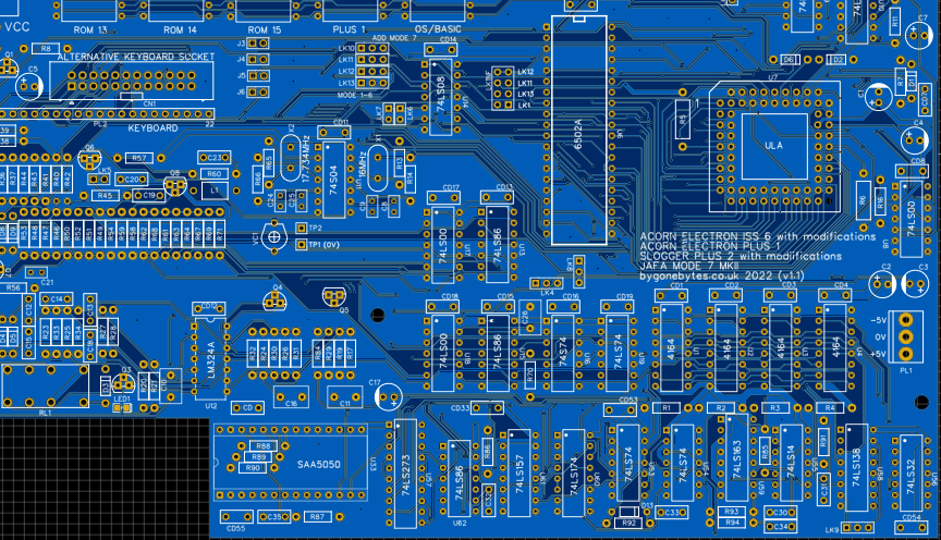
Jafa Mode 7 MKII added to the clone board, the cutout leaving room for the speaker and MRB switch.
Assembly
While waiting for the board to arrive I gathered as many parts as I could so I could get a good start on the assembly. Once again I'll assemble the PCB then add in the IC's for each section, the Electron, the Plus 1, The Plus 2 then the Mode 7 MK2.
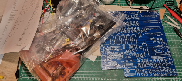
The bag of parts and the PCB.
Soldering begins..
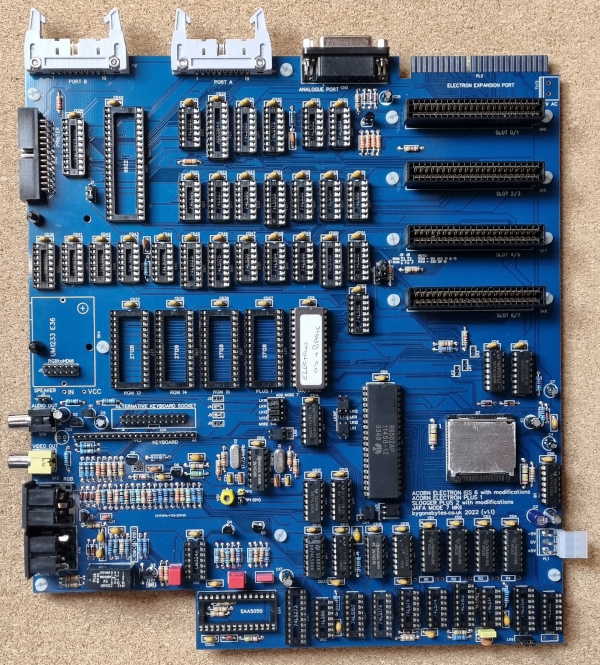
Waiting on only four capacitors to finish the soldering.
All the physical issues with the first board are fixed with the parts fitting first time including the fixing holes for the cartridge connectors. I also added more holes to provide extra support to help when plugging/unplugging ROMs, processor and cartridges.
As before I powered up to test the 16 and 17.734MHz oscillators - both OK so I populated the board with the Electron components ready for fitting the last few capacitors.
You may have noticed the ULA clip/heatsink is not an original, I only had one which I used on my first Clone so I made a couple of copies for my spare ULA's.
Testing
The four capacitors didn't arrive so I checked what effect they would have if I switched on without them - two are in the cassette interface, one for decoupling and the other is in the UHF circuit so they're not required to start testing. I went ahead and populated the board with the components for the Plus 1, Plus 2 and the Mode 7 Mk2 adaptor. Switching on I got the red/yellow block screen so I re-seated the ULA and it was up and running. (The blue dot on the screen is a reflection of the Caps Lock light, I later fitted a piece of black heatshrink over the LED to prevent this.)
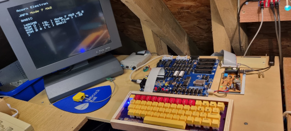
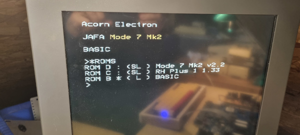
I was a little disappointed when I issued the *MODE7ON then BREAK and *ROMS as some the characters weren't as rounded as I remember and some had flickering ghosting pixels, also some of the characters had the first column missing.
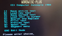
Next I tried Wordwise Plus..
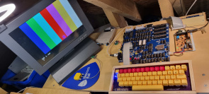
then alarm bells started to sound in my head! The colours are not right, the magenta and cyan are transposed! I traced this back to an error in my original drawing that I didn't pick up through checking, the red and green from the SA5050 are crossed. Unfortunately the fix required two short wires.
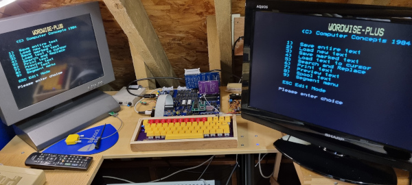
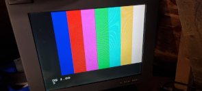
Colours sorted.
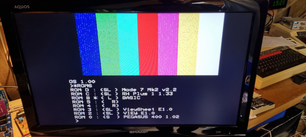
I installed the RGBtoHDMI to see how it handled the MODE 7 and initially not too well, I'll need to spend some time to see if I can improve the RGB signal then go through the RGBtoHDMI setup menus.
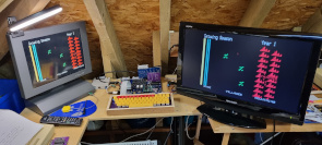
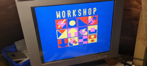
Trying out some MODE 7 software (Kingdom and Workshop) and it looks not too bad..
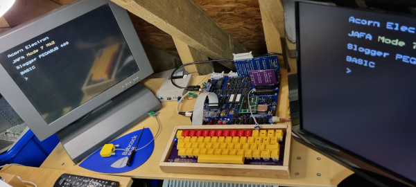 Looking better after running for several hours.
The full system including a Turbo Card.. need to change that to a MRB.
Looking into poor picture quality
This is the problem:
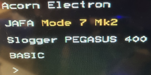
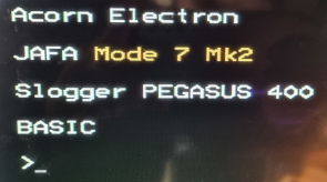
Looking at the left photo some of the characters, especially E, J, M and A have the left column missing and an extra thick one on the right. It is not the nice smooth font you'd expect from Mode 7. The photo on the right shows a much improved font.
The circuit that generates the Mode 7 characters:
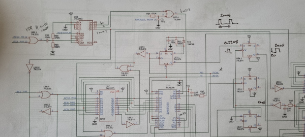
The IC's top left, U59 & U62.4, along with R91 and C31 generates the 6MHz required for the SAA5050 character generator. The mark/space ratio requires to be 50:50 to achieve a symmetrical font but with the 74LS IC's this was more 60:40. Changing the IC's to 74ALS versions corrected the mark/space ratio and changing R91 to a muli-turn preset allowed me to fine tune fringing on the characters.
I then looked at the RGBtoHDMI picture and changed one option in the sampling menu:
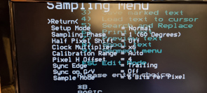
Sample Mode = changed from 3 bit per pixel to 6 bit per pixel.
I found I could have very clear and steady white text in Modes 0,3 and 7 but colour text in mode 7 it would 'fringe' so I re-calibrated with a colour bar pattern and I could get perfect coloured text and background but white text in mode 0 3 and 7 would 'fringe'. I think it'll take a fair bit of time to get it fully calibrated, at least I know I can get a good picture.
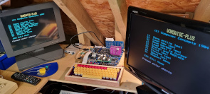
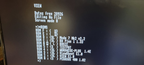
Solidly good Mode 7 and Mode 0 through RGBtoHDMI.
Version update
This will be my last update (famous last words!) so version 1.2 changes are:
1) Correcting the red/green error on the SAA5050
2) Fixing U28 silkscreen to read 74LS260
3) Mode 7 - change IC types and labels for U59 and U62 - ALS versions.
4) Mode 7 - change R91 to a multi-turn preset.
5) Remove IC14 - not required.
6) Remove Links 10 to 13 - not required.
7) Add mounting hole near slot 0/1 - not reliant on slot mounting holes to fix PCB to base.
8) Added USB header (power only) to power Gotek drive.
9) Added labels on LK9 - A & F for ULA type.
....
Miscellaneous
I made up another keyboard which will be used purely for testing but it's a bit fragile on its own so I made a chunky case out of left over plywood from my Maplin 5600 synth case - solid!
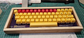
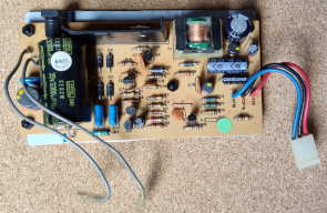
and bought a another ex-Elk PSU and mounted it on an aluminium plate for stability, again just for testing.
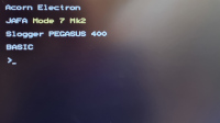
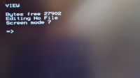
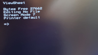
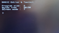
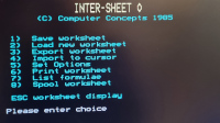
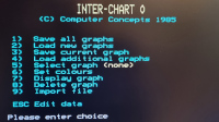
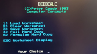
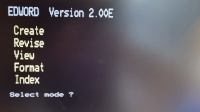
Trying out some ROM software in Mode 7 on the Electron
Footnote: I ordered my Mode7 MK2 as a kit from Jafa systems on the 29th May 1990. When built I found some problems with it; the tearing of characters, it would occasionally not start, the Slogger *ROMS command from the AP2 ROM wouldn't work and it wouldn't work with the E2P second processor.
I wrote to Jafa (John Wike) who suggested the alterations to R2 and C7 and explained I needed Mode 7 ROM v2.1 and E2P ROM v2.4 combination for E2P compatibility and that I should send one or other of my ROMs for re-programming and also to send an image of the Slogger AP2 ROM so he could look at the *ROMS issue. Shortly after I received a new Mode 7 ROM, presumably v2.2 which fixed the Mode 7 *ROMS and E2P compatibility.