Acorn Electron Refurbishment and Upgrading (2021)
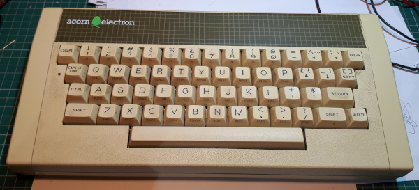 This project is to bring back an unloved Acorn Electron from it's loft/garage condition to a fully functional and useful piece of retro kit. I will give it a good clean inside & out and add a few
useful upgrades. The upgrades will boost its speed, add disc storage and some cartridge slots.
The Electron I bought from eBay for £34. It came all by itself, no PSU, leads or manuals. So initially I had to find a PSU and make an RGB cable from my collection of Bits & Bobs. An old Pi-Top PSU
that is rated at 18V 3A DC will do nicely along with a home assembled RGB lead made up from a couple of 6 PIN DIN connectors and a metre or so of old CAT5 cable.
After the clean up the add-ons I plan to add are:
1) The OSTC, an Open Source Turbo Card that fits in place of the 6502 Processor inside the Electron.
2) The Minus One, an Open Source cartridge board that plugs into the expansion slot on the Electron.
3) The Slogger Pegasus 400 Disc Interface with Gotek Disc Drive Emulator which plugs into one of the Minus One cartridge slots.
I've documented most of the work involved using photos..so here goes..
Sorting out cables, PSU etc, unpacking and cleaning.
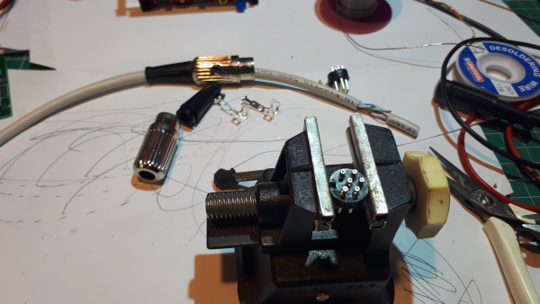
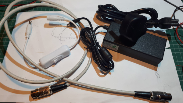
Making the RGB cable and collecting together other items such as the PSU and an ON/OFF switch.

The Electron just out the box.
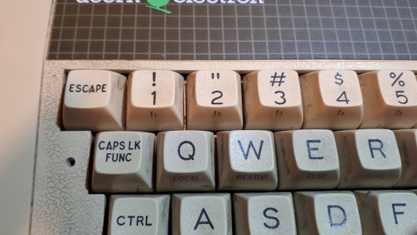
At first sight it looked in good condition, a bit grubby with years of use and storage.
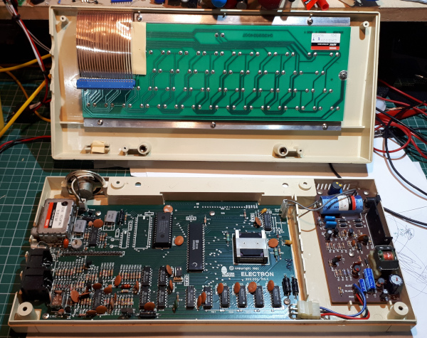
On opening it looked a very clean issue 4 Electron.
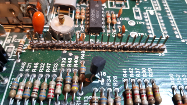
But a closer look revealed a fair bit of dust collected around the components.
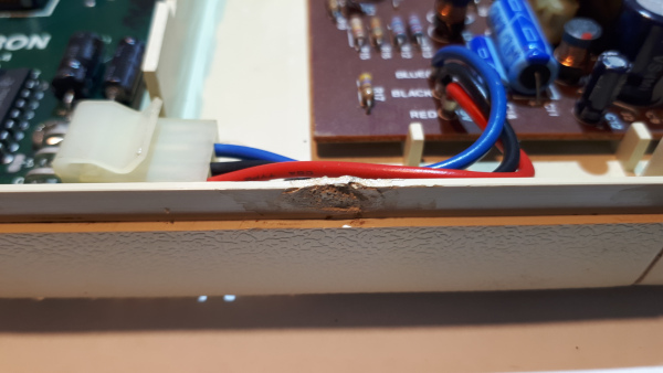
And a little damage on the front of the case. The deformation looks like melted plastic which may have originated from the factory as it's not seen from the outside and when I was removing the
case screws they felt as if it was the first time they had been removed.
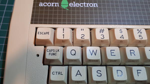
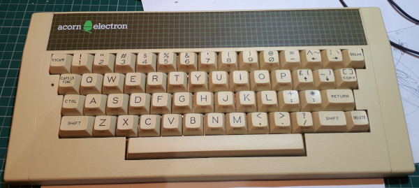
As this is all about reburbishment you'd have thought I'd have taken some pictures of the Electron keyboard dismantled during cleaning but I didn't! All that was necessary was to clean the case
and the key caps using foam cleanser. With the key caps removed I could see a little discolouration but not enough to go through a retro-brighting process.
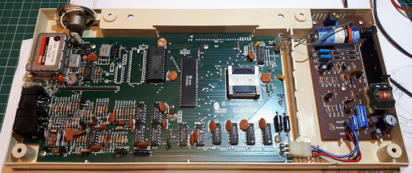
The circuit board just needed a good brush down to remove the layers of dust.
A common issue with Electrons is that over time keys become unreliable with some intermittent and others don't work at all, Once again I was lucky with this one as all the keys were still
working with no contact cleaning necessary.
Preparation for my first upgrade.
The first upgrade will be to install a new Turbo card in place of the 6502 processor, this requires removing the existing 6502 and replacing it with a socket.
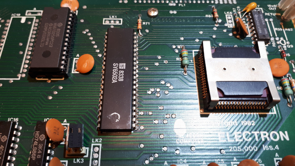
The 6502 processor to be removed.
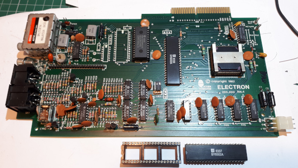
First remove the Electron motherboard from the case, unplug the DC power cable, the 19V AC wires and the speaker cable. Then remove the four screws then the motherboard will just slide out.
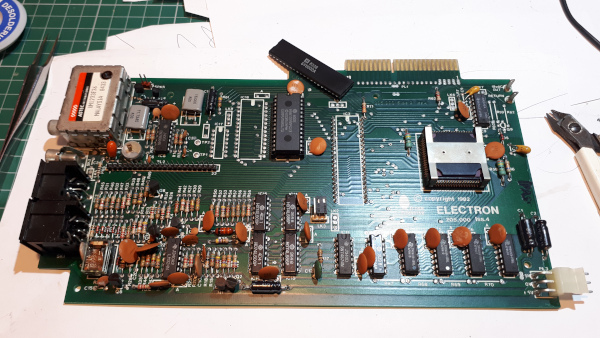
Removing the processor involves cutting it's legs, !Warning do not do this if you don't have working spare 6502 processor!
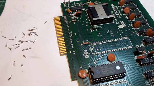
removing the legs from the PCB,
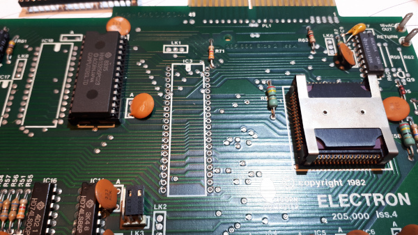
cleaning the holes,
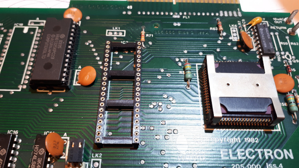
fitting the new socket,
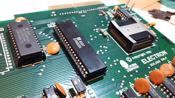
and then the 6502 processor.
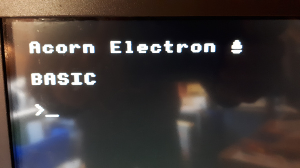
Now reassemble the motherboard, case and keyboard as the next important step is to see if it still works! and it does!
Upgrade No.1 - The Open Source Turbo Card (OSTC).
The first upgrade is to install the new OSTC which has just made an appearance on Stardot and github. I used the Gerber files available on github to order the 4 layer
board from JLCPCB which cost just £5.16 plus postage for 5 boards.
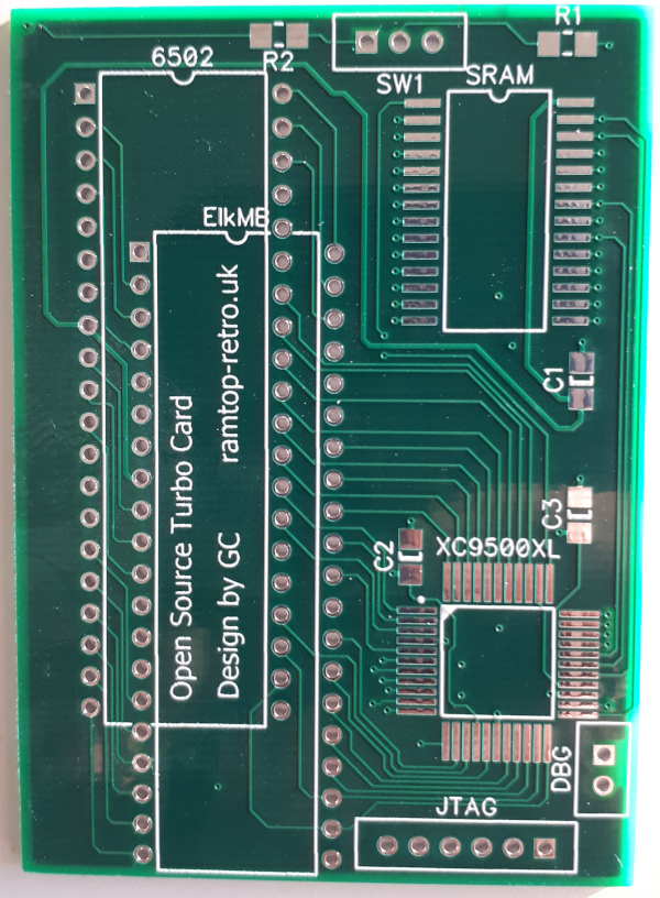
The OSTC PCB.
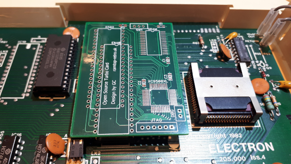
This picture shows a mockup of where it will sit in the 6502 processor socket. It can be seen in the picture that there is a link that might prevent the OSTC from sitting down in the socket
correctly. Once the board is assembled I'll check if it needs to be replaced with a lower profile link.
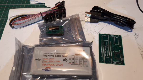
This is where I delve into unknown territory, I have maybe twice used surface mount components and I've never transferred data to CPLD devices. To prepare for this I have ordered a magnifying
lamp to help me see what I'm soldering, a 0.4mm tip for my soldering iron and a flux pen. On the software side I had to research the Zilinx XC9536XL CPLD and how to transfer the data to the device. What I
believe is needed is the xilinx ISE software, I chose the Windows version, and a Platform Cable.
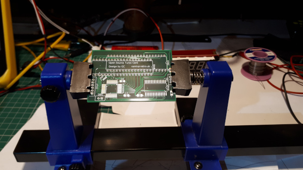
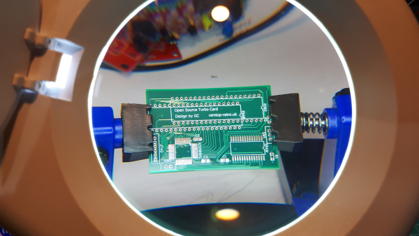
Preparation is complete and I'm ready to try some soldering. Using my new magnifying certainly makes it easier to see but I have to get used to the new eye - hand co-ordination..
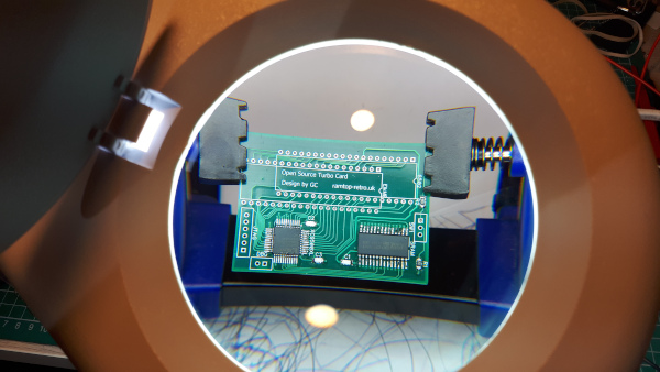
First Components soldered..
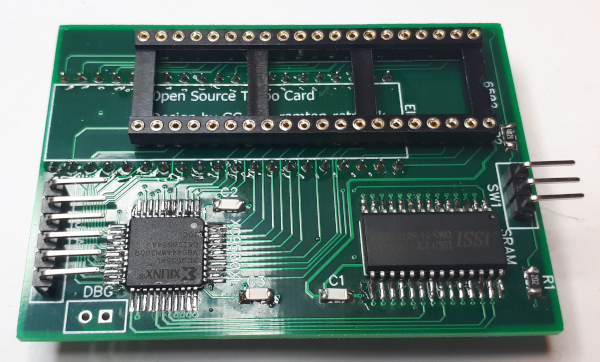
The board is now fully assembled ready for the CPLD to be programmed.
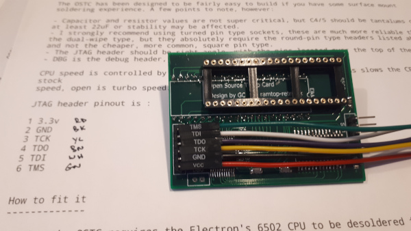
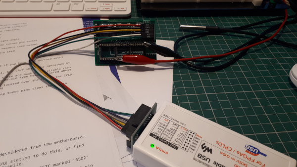
Connecting the OSTC board to the platform cable for programming. Initially I could not get the cable to connect due the the reference voltage being reported as missing!, I had assumed
the reference voltage originates from the cable but it turned out it comes from the OSTC board. Once I twigged that it only took a couple of temporary wires to false feed 5V onto the
board and up it came.
To copy the program to the CPLD open the Xilinx ISE program then select 'Impact' from the Tools menu. Initially Impact was configured for a Parallel cable device and not the USB Platform Cable, change this
in the output menu.
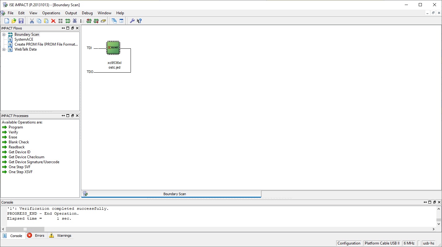
Do a Boundary Scan then select the jed file.
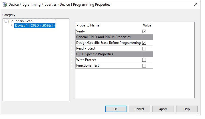
Next select program and select OK on the next window.
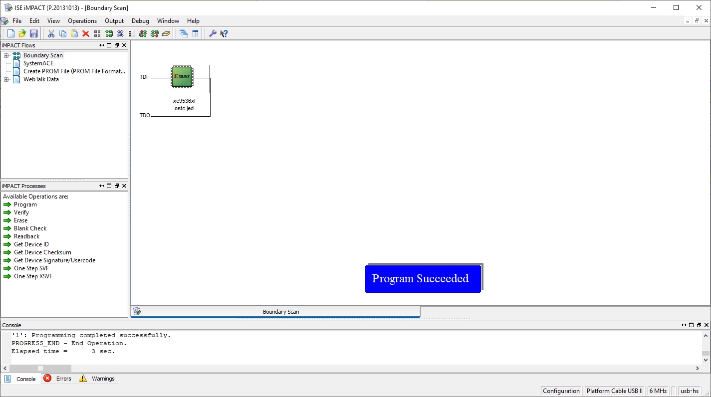
You should then be informed that programming was successful.
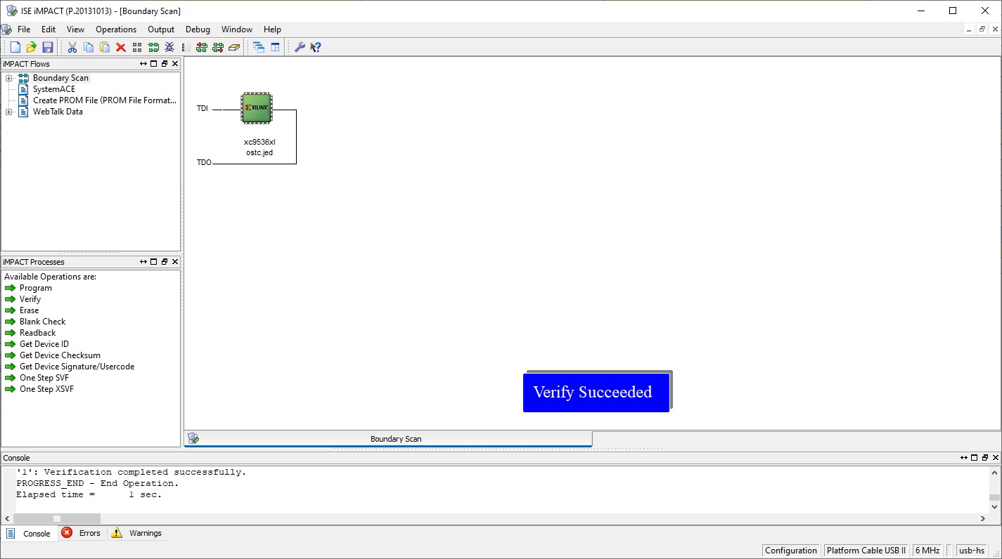
I then did a Verify just to confirm everything was OK. Lastly I disconnected the cable fron the Output menu.
Next was to make and fit the turbo switch cable.
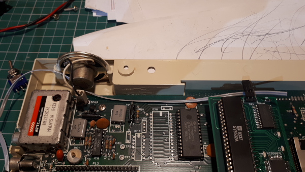
Measure the length of wire required.
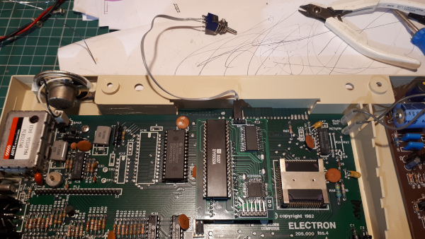
and solder the wire to the switch and crimp (or solder) a couple of Dupont sockets on the other end.
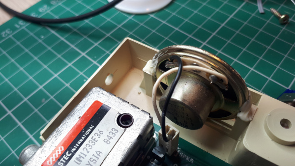
Drill a hole in the side of the Electron for the switch.
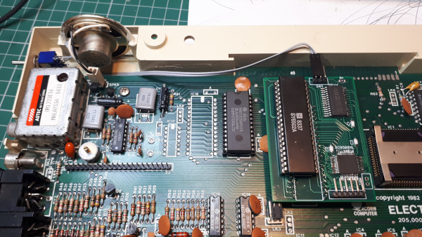
Fit the cable into the Electron.
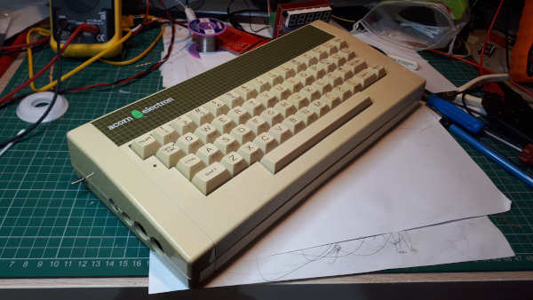
The Electron is reasembled ready for testing.
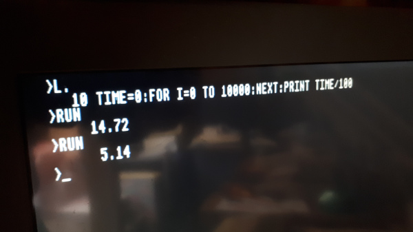
On switch on there is no way of telling which mode it is in so running a simple speed test revealed it was in mormal mode. Switching it to turbo shows a 3 X speed increase.
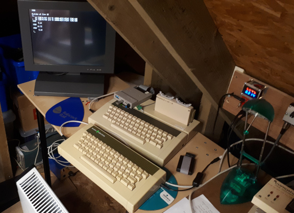
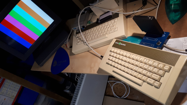
The front Electron with the new OSTC under test.
Upgrade No.2 - The Minus One (a Plus 1 alternative).
A year or so ago I saw some bare white PCB's called 'Minus One' for sale on eBay, they were described as providing three cartridge slots for the Electron - I knew nothing about this board
so I let it pass me by.
Recently I have been failing miserably at buying a Plus 1 one on eBay - £50+!!, so for this project I am now thinking back to the Minus One board. Full details for the build can be found on GitHub
so I have ordered some boards from JLCPCB - 5 for £1.54 plus postage!
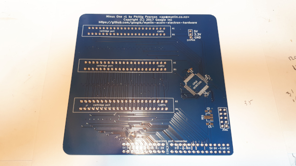
The bare board.
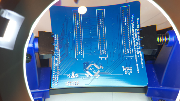
Set up for soldering the suface mount components.
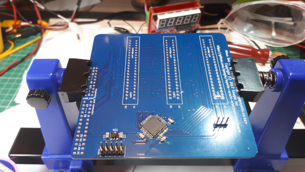
The components are now soldered and the board is ready to test.
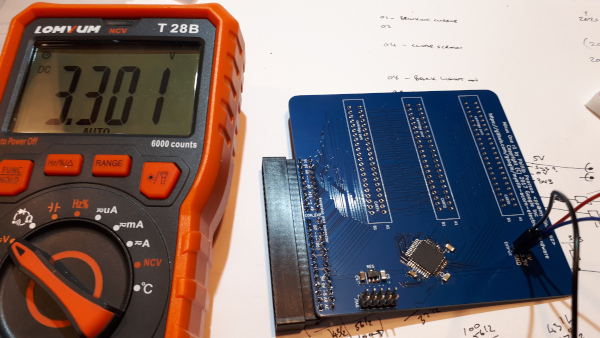
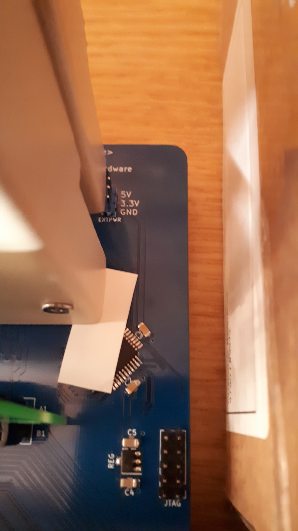
Before starting to program the board I tested the 3v3 regulater as it is needed as the reference voltage for the programmer - bang on 3v3. This board is well thought out as it has a header for feeding
an external 5V. - no need to plug it into an Electron to program.
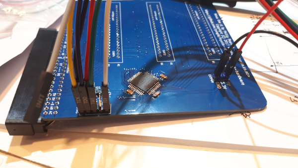
Connecting the Platform Cable to the Minus One.
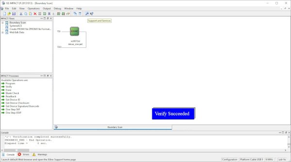
The Minus One uses the same process to program as the OSTC so I won't include every step, see OSTC above, just that it programmed and verified successfully.
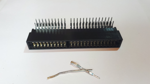
The 52 way edge connector needed one small modification and that was to remove the pins in the space of the 'key'.
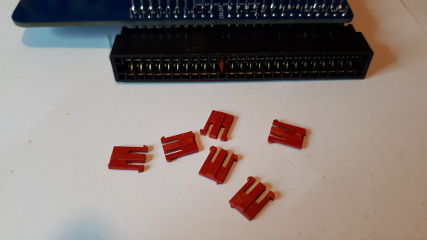
I found an old bag of edge connector end stops which are perfect to use as the key. It also aids alligning the board with the Electron.
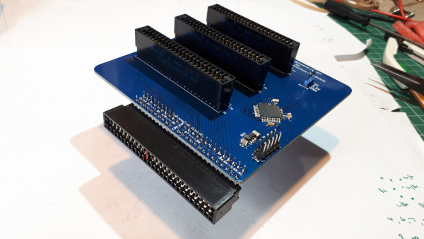
The 44 pin edge connectors soldered on place.
One Edge Connector was enough to try out the board. Here it's working with a ROM cartridge running my Pattern Generator ROM.
With the Minus One only held on the rear of the Electron by the pressure of the edge connector it is difficult to plug in or remove any cartridges. As far as I can see there is no case available
so I built a plate to mount the Minus One on which will bolt into the Plus One mounting holes to give it rigidity. Unfortunatetly there are no fixing holes on the PCB so I selected a three points
to drill that doesn't t affect the tracking.
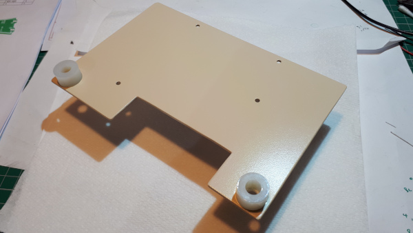
The painted plate with 10mm pillars to fix the the Electrons Plus 1 fixing holes.
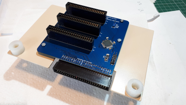
The plate with the Minus One mounted.
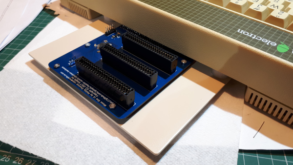
The plate with the Minus One attached to the Electron.
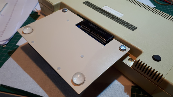
The underside of the plate with the Minus One attached to the Electron.
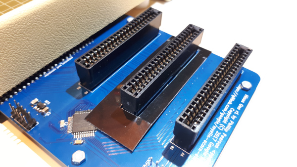
As some of the components are close to an inserted cartridge I made a small shim to protect both the components and the cartrige.
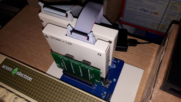
The Minus One slots fully populated with Disc Interface, ROM cartridge with User Port and a basic ROM cartridge.
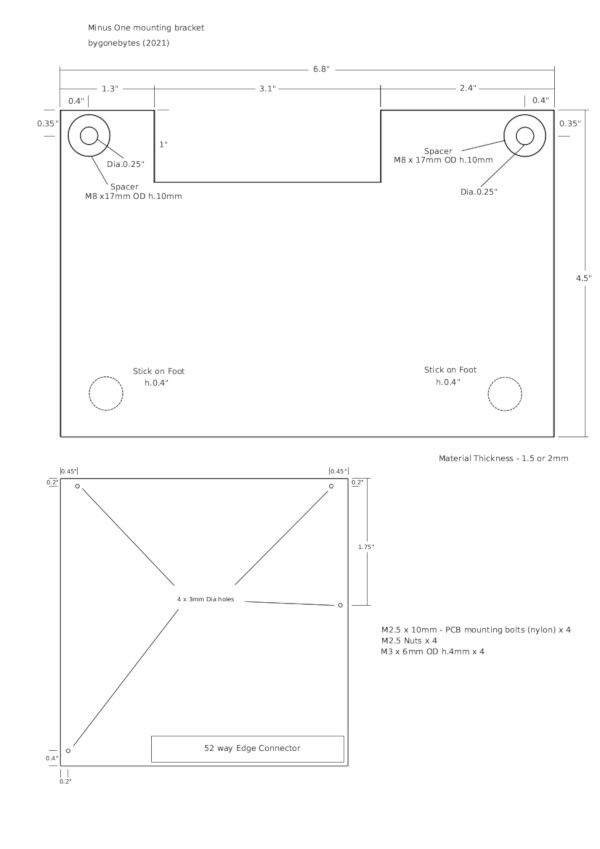
I've produced a pdf showing the dimensions of the Minus One mounting plate.
Upgrade No.3- Slogger Pegasus 400 Disc Interface and Gotec Disc Drive Emulator.
When the boards arrived I just had to assemble, test and 'blow' and EPROM with the Pegasus utilites.
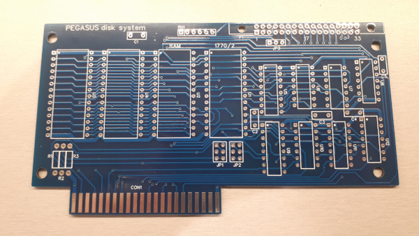
When working on reviving my Acorn Electrons I re-laid the PCB for the Slogger Pegasus 400 Disc Interface so for this refurbishment I just had correct an earlier error on the silk screen
and order new boards. I chose to have the new boards in blue, an odd method of version control but it works for me.
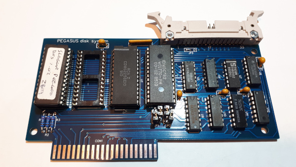
The assembled board.
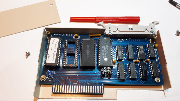
and built into a home made case.
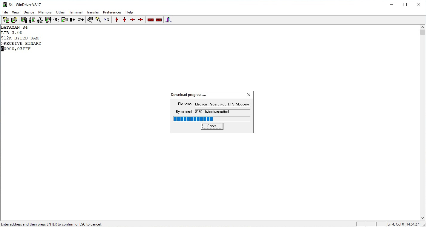
Transferring the Pegasus ROM image to the programmer.
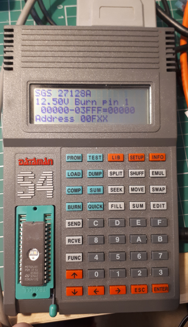
and burning the EPROM.
The Disc Interface needs a disc drive so I've chosen to buy and convert a basic Gotek Disc Drive Emulator. These drives are available ready to go on eBay for around £45-£60 but I thought I'd convert one
from the basic unit by adding a rotary selection switch, a small speaker, an OLED display and flashing the latest version of Flash Floppy. There's a lot of steps to do this but all of
them are small and fairly simple so there's quite a few photos to show the whole process.
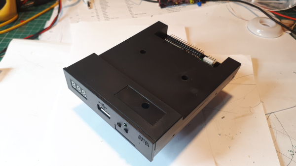
The Gotek drive that will be updated.
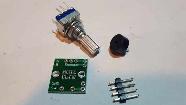
Preparing the Rotary Encoder switch (EC11).
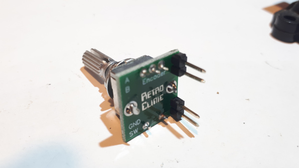
Retro Clinic sell small boards and headers for a few pence to solder the switch on to.
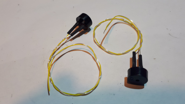
Prepare a small sounder with a couple of wires.
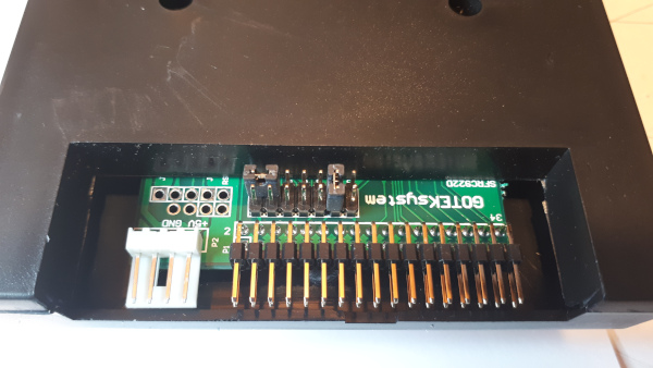
Identify where a five pin header has to be soldered.
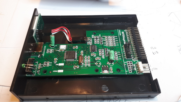
Take the lid off.
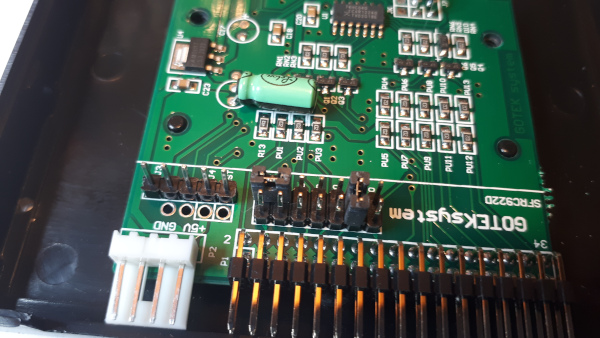
Remove the board and solder on a 5 pin header.
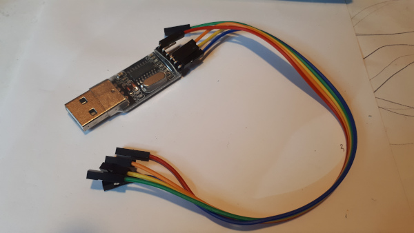
This stage involves re-flashing the on board firmware. For this a USB to TTL adapter is required.
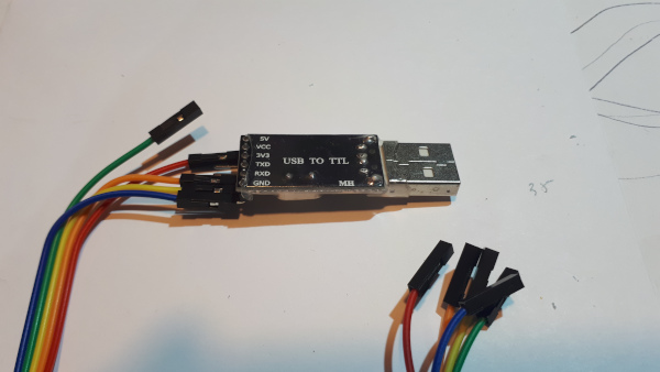
Connecting the jumper wires to the USB TTL adapter, the data and the 5V power supply.
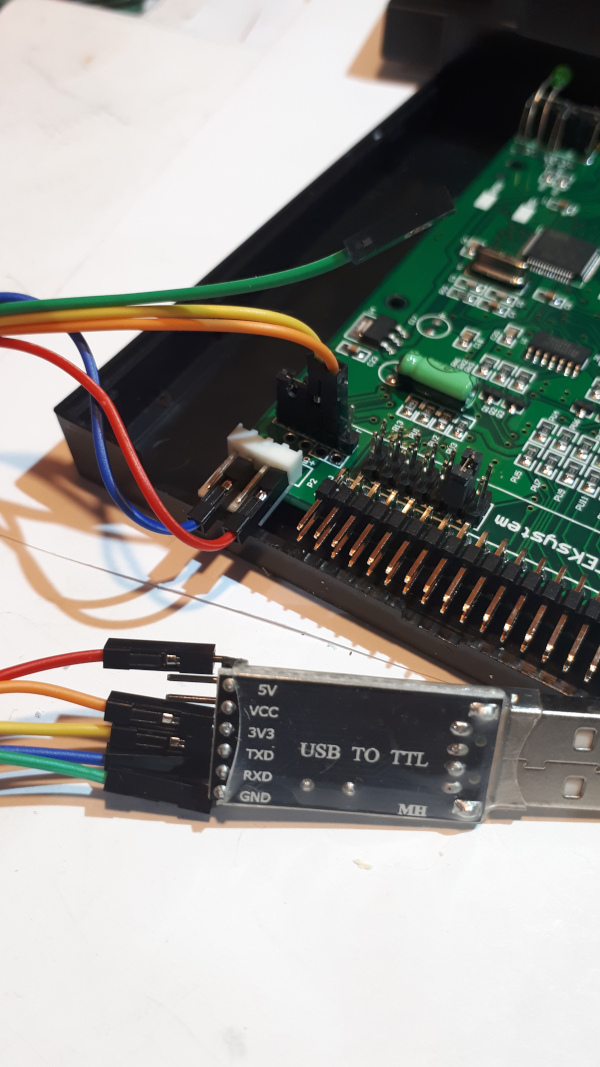
Connecting the jumper wires to the Gotek drive, the data to pins 3 and 4 and a shorting link to pins 1 and 2.
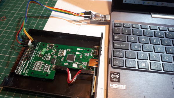
The Drivers for the USB TTL adaper should be installed on the PC before plugging it into the computer.
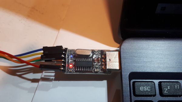
Normal indications on the USB TTL adapter.
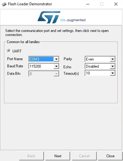
Download and install the ST Flash Loader program. On the opening screen select the COM port the USB TTL adapter has been assigned and select Next.
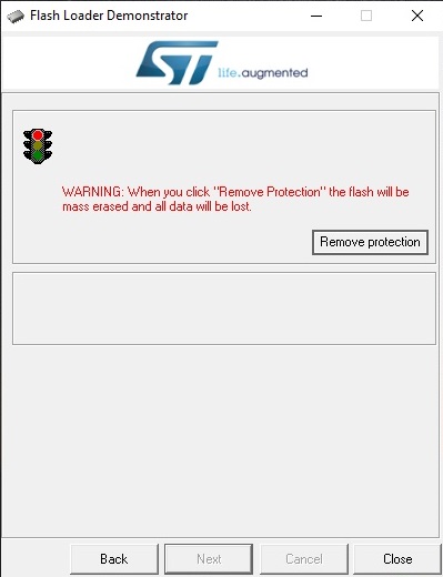
The step is to remove the Flash protection. Selecting Next will do this.
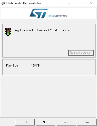
When complete it will repond with 'Target is readable'. Select Next.
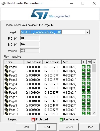
Select the target device, is is generally the default selection. Select next.
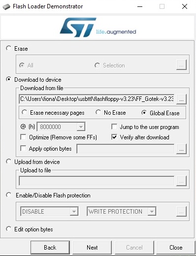
Now select 'download to device' and navigate to the Flash Floppy hex file. (downloaded from the Flash Floppy web site.)
Select 'Global erase' and Verify after download'. Select Next.
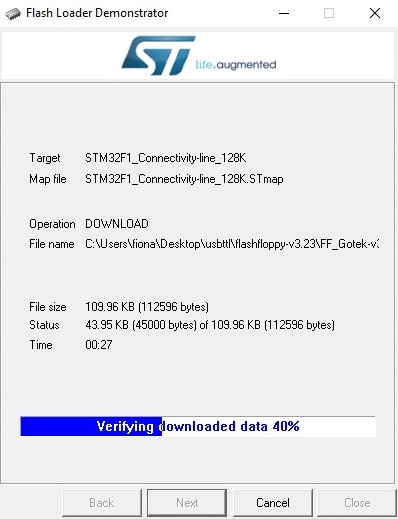
It will proceed to download the firmware to the Gotek and Verify that it has completed correctly.
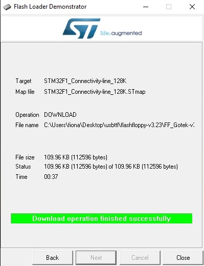
Then it will say that the operation has been successful. Close the window and remove the USB TTL adapter from the PC and the Gotek drive.
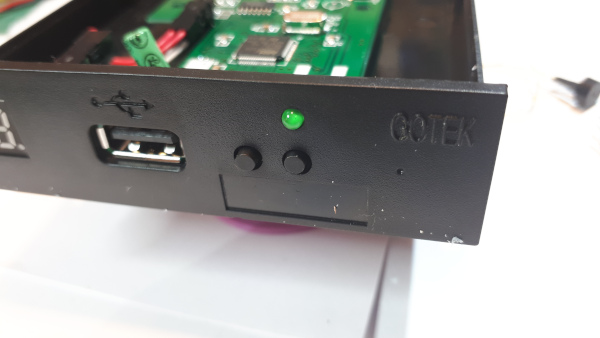
Next a hole needs to be drilled for the Rotary Encoder Switch, by design there is a starting indentation on the front of the drive.
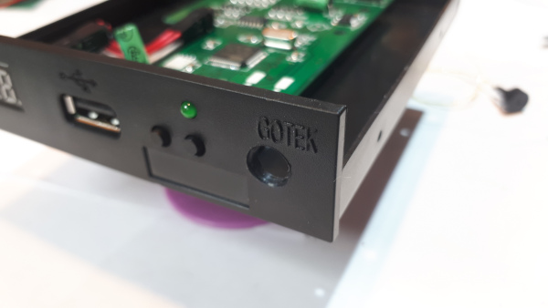
Measure the size of hole required and drill, mine required a 7mm hole.
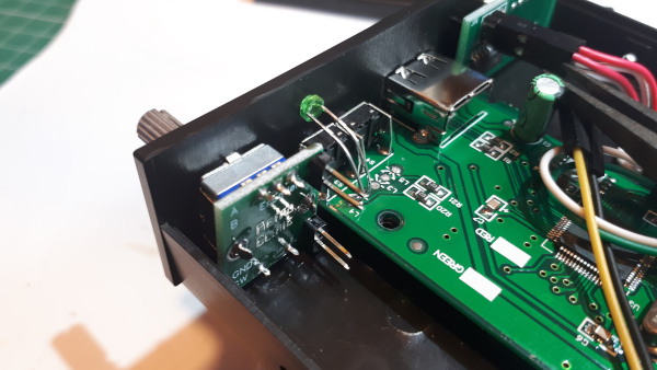
Mount the Rotary Encoder switch in the Gotek case.
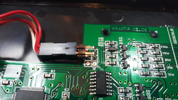
Look for the two pads where a 90 degree header has to fit for the Rotary Encoder jumper.
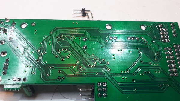
Clean out the holes with a soldering iron and a solder sucker.
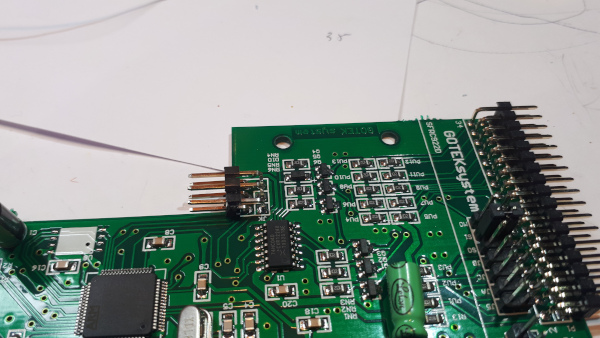
Solder the 90 degree header in place.
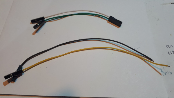
Make up two sets of jumper cables, one for the Rotary Encoder and the other for the Switch.
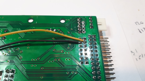
Solder the Switch wires to the underside of the board.
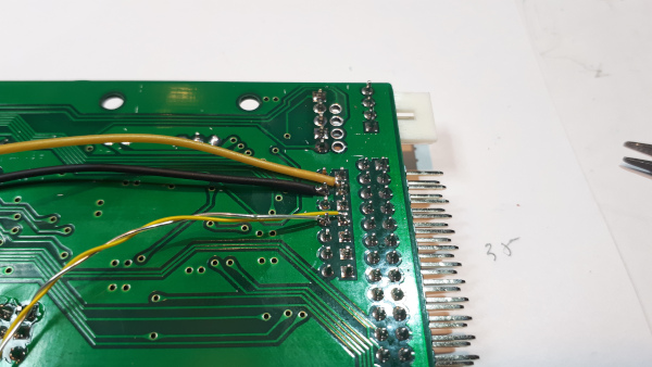
Solder the Speaker wires to the underside of the board.
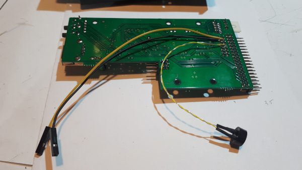
Board with Switch and speaker wires soldered in place.
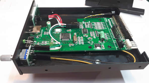
Connect the jumper wires to the Rotary Encoder board. I had the green & white wires the wrong way round as it counted down the files when turning the control clockwise, simply
swap the green & white wires at the switch end to correct this.
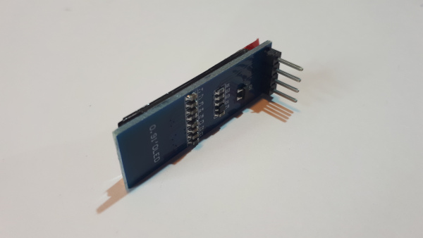
Now moving on the fitting the 0.91" OLED Display.
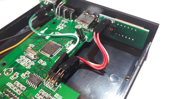
Remove the 7-segement LED display. Unplug from board and push out the display from the front.
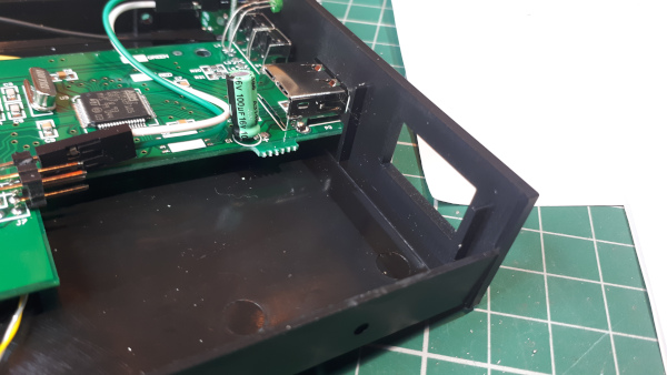
Identify the two mounded webs on the front of the case.
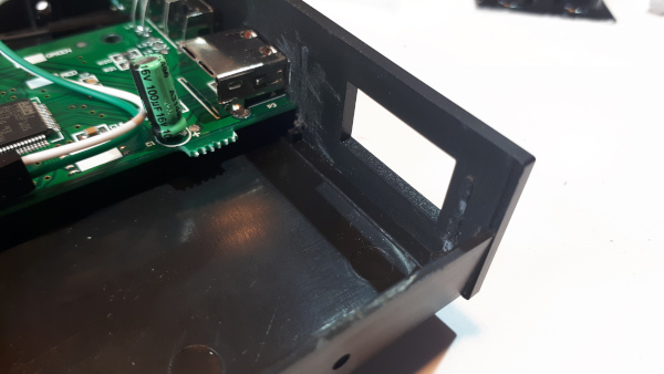
Remove them and file flat.
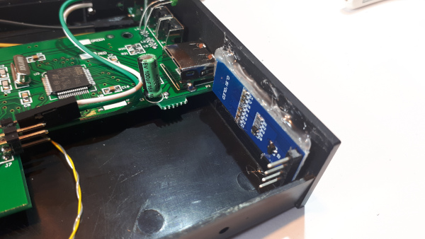
Hot glue the OLED display in place. Careful alignment is necessary before gluing.
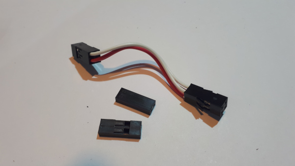
remove the cable from the old LED display. This one came with the wires in a 2x2 headshell, at one end the contacts should be removed and placed in either a 1x4 or two 1x2 headshell
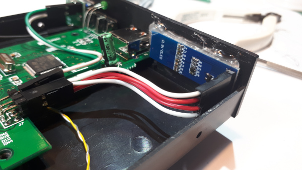
OLED cable connected between PCB and OLED display.
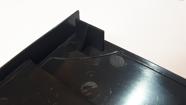
There is another web on the lid of the Gotek case that should be shortened by about 3mm.
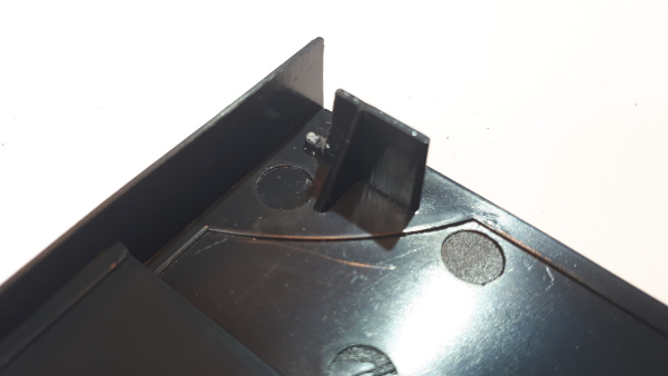
Just trim and file.
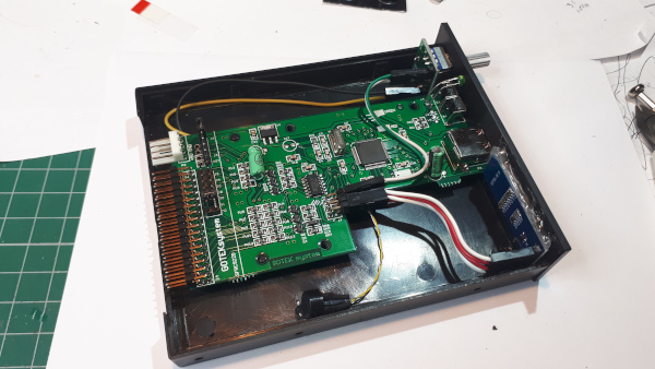
And that is the modifications complete.
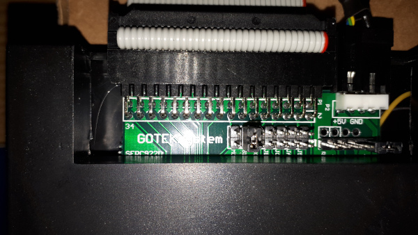
The default setting for the drive is drive 1, the link is set to S1.
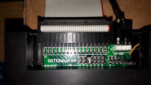
change this to S0 for drive 0.
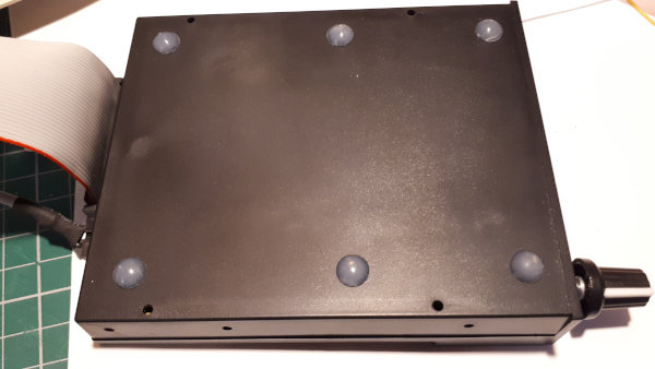
And some finishing touches - some feet.
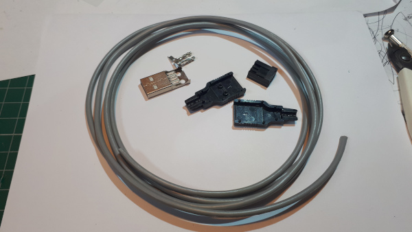
Next I made a USB power cable for the drive as it suits my power distribution.
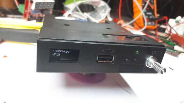
Switching on the Gotek for the first time.
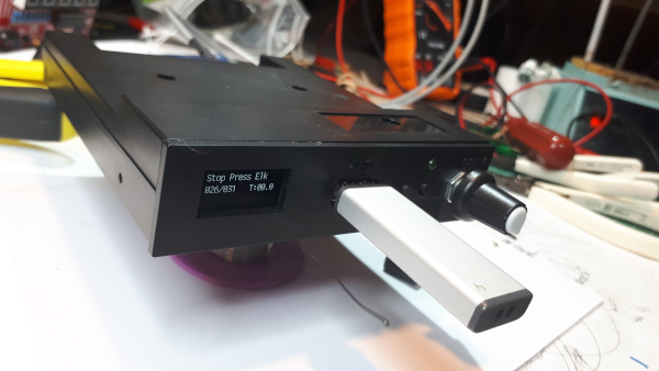
and testing it with a known USB Drive. the drive contains the Flash Floppy configuration file and some disc images.
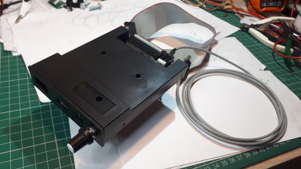
With a 34w ribbon cable the drive is ready to plug into the Pegasus Disc Interface.
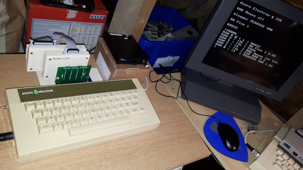
The final refurbished and upgraded Electron
The Electron has been given a good clean inside and out and I've removed the processor and fitted a socket so I could install a Turbo Card (OSTC) giving some extra speed. Along with that I've expanded
the Electron with a Minus One cartridge slot expansion board and a Slogger Disc Interface with Gotek Drive. The Minus One is fully populated with cartridges, the rear slot has the Disc Interface
with the DFS and E2P ROMs (0 & 1), the Middle slot has a ROM cartridge and User Port with AMX Mouse support ROM and a spare ROM Bank (2 & 3). The Near slot has View and The RH Plus
1 ROMs (4 & 5), I'm trying out the RH Plus 1 ROM as it will give me some useful utilites for SRAM and the *ROM command.
Problems encountered
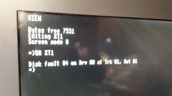
The first problem I came across was when I tried out the View word processor, occasionally I would get a Disk Fault when saving files. The disk fault, 'Disk Fault 04..'
is not one I recognise and I can't find any details regarding it. I tracked the issue to the Minus One/Pegasus Disk interface, the Pegasus would work perfectly
in a Plus 1 but not in the Minus One! trying another Pegasus Interface in the Minus One worked without problems. I'm guessing that there is a the tolerance issue between
my original combination of Minus One and Pegasus Interface. For the time being I've swapped the two interfaces over but when I get some replacement IC's I'll continue
to look for the component that is causing the issue.
The Disk Fault reported.
Following up on the Pegasus problem - When the replacement IC's arrived I switch on the Electron and nothing happened! no sound, no LED etc. An obvious short circuit on the PSU.
I switched off, unplugged the Pegasus and switched on again - the Electron was OK. Taking the Pegasus to the workbench I powered it using a bench supply with a current limit of
500mA, more than it requires to run normally, and it took the 500mA. The short circuit was on the board! Only the EPROM's, RAM and 1770 IC's are in sockets so removing them one at a time and
checking for the short did not reveal the culprit.
Next I checked over the entire board for stray solder splashes or anything that could cause a short - nothing. This left me with the
task of unsoldering each component one at a time until I found which one is faulty. As capacitors are fairly well known for failing I started at C1 and got very lucky, checking the capacitance,
none, then the resistance, less than nine ohms. Checking the Pegasus board again with the capacitor removed it was drawing 60mA, great. I fitted a new capacitor and refitted the EPROM's etc.
and tried it in the Electron, all was working great. I then tested for the 'Disk Fault' issue and that had been fixed too. The capacitor must have been intermittently failing then failed completely.
Another issue is the placement of components on the Minus One PCB, they're just a bit close to the cartridge slots. see photo below. I am thinking about adding a small
shim round each cartridge socket to restrict the depth a cartridge can be inserted, this will prevent any risk of a metal cartridge case from shorting against
the components. I'll also look for a cap to cover the links that are very close the cartridge edge.
A very close fit.
