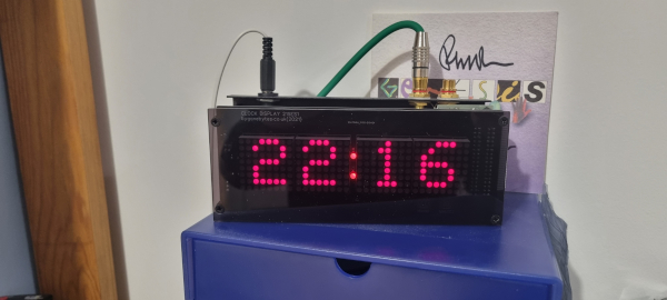
Workshop Clocks
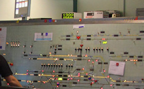 I have been thinking about buying a couple of clocks for my workshop when I came across a box of old circuit boards from the 80's, these included a few Train Describer Display Modules from the time
I worked for British Rail ScR. Back in the day these modules were used in the ScR Train Describer as well as Signal Box Panel Clocks.
I have been thinking about buying a couple of clocks for my workshop when I came across a box of old circuit boards from the 80's, these included a few Train Describer Display Modules from the time
I worked for British Rail ScR. Back in the day these modules were used in the ScR Train Describer as well as Signal Box Panel Clocks.We converted a TD display module to a clock by removing it's Micro-controller and replacing it with a daughter board with the 8748 micro-controller reprogrammed as a Primary clock, the daughter board also had the capability of transmitting the time over a two wire circuit to secondary display modules keeping them all synchronised. The clocks had their dot matrix displays replaced with larger 2" versions.
I'll be doing the same thing but with just two clocks (six were used on Signal Box Panels) and 1.3" displays. The original circuit diagrams for the display module and clock daughter board are below.
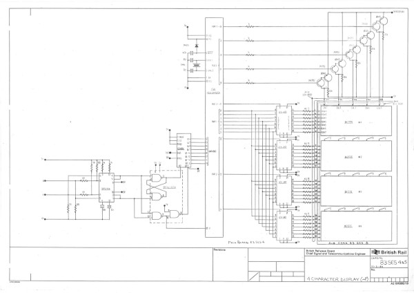
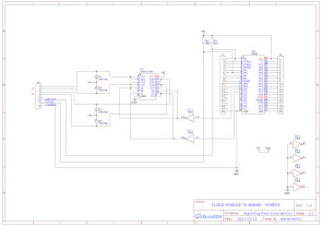
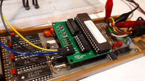
I re-drew the clock daughter board fixing the errors and sent off for PCB's, then part built one to confirm it worked ok. The 8748 micro-controller was programmed using an Arduino & Shield, see project here.
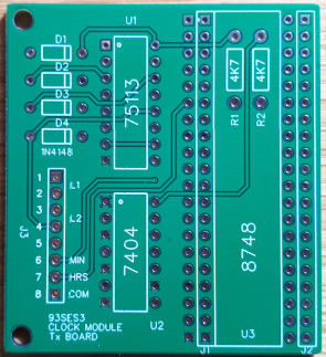
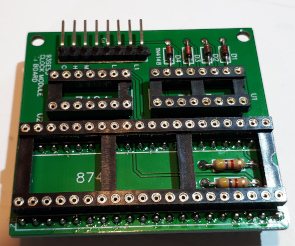
The daughter board.
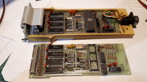
These are the two Display Modules I'll be using, one is from High St. Junction Signal Box 1983-1989 and the other Cathcart Signal Box 1986-2007.
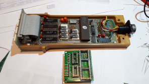
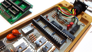
The display being prepaired for the daughter board. The two large tantalum capacitors prevent the board from siting neatly in the socket so a riser was needed.
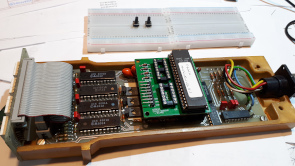
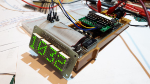
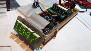
After fitting the daughter board into the display module micro-controller socket I switched it on. It worked! but as can be seen the second character from the right has a missing a column of LED's on the left hand side, this turned out to be a dry joint on the display matrix - easily fixed.
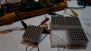
The new display matrix is an 8x8 matrix, a bit big for my purposes but I can use just 5x7. The unused columns will just act as spacers between the characters. The dot matrix displays can be either illuminated red or green as shown here so I'll design the new matrix board to make it easy to select which colour to use.
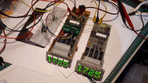
The clock daughter board is complete and is now sending the time data to the secondary display module, the one the right.
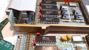
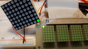
The two display modules have different current limiting resistors, 15R for the High St. DLG 5735 dot matrix displays and 10R for the Cathcart LTP305G displays, obviously each type requires different currents to achive a similar brightness. The same applies to the new KYX-1088AGH displays which require about one tenth the currrent, I'll set up a display matrix/display card on breadboard to help select the correct resistor value. As the LED's are multiplexed it won't be possible to measure the current with a meter, I'll have to measure the volt drop across the resistor with an oscilloscope and calculate the current using Ohm's law. The photo on the right shows the DLG5735 and the KYX-1088AGH displays supplied the the same voltage but fed through a 1K and 10K resistor respectively.
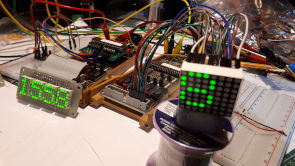
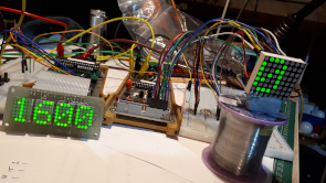
I set up a single display using a breadboard with jumper wires and included 390R resistors in series with the 15R resistors on the display board. The volt drop across the 390R resistors measured 850mV so the current per LED calculates at 2.2mA. With the old DLG5735 display showing a full rastor the current works out to around the 1.4A, a typical time display around 570mA. With the new display the current works out at 308mA and 125mA respectively, a fantastic power saving!
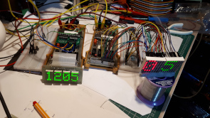
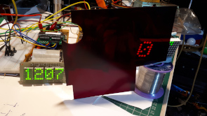
I've been looking at the Red/Green option while I'm waiting for the display front to arrive. Either one looks ok, the only issue is finding filter material for the front. The red filter in the picture is an RS Components supplied 'Glarecheq' optical filter, Stock No. 588-190, from 40 years ago!
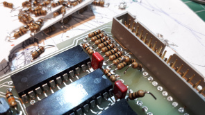
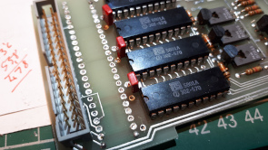
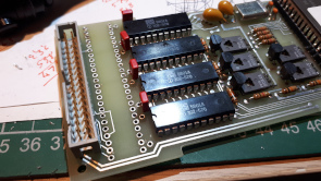
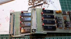
With the Row current limiting resistor values selected, 390R, I removed the existing resistors from two display boards. Hindsight Engineering tells me I should have added the resistors to the LED Dot Matrix boards (already ordered) thus saving the removal of these resistors!
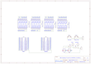
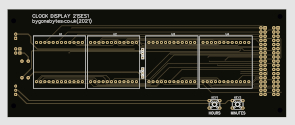
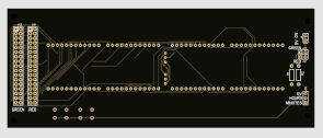
The idea for the clock assembly is that it will form a sandwich with the filter first then the display front and then the display module all mounted on pillars. I have included a couple of red/green LED's on the display front as a colon between the hour and minute segments.
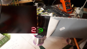
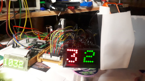
Looking at a couple of filter options, the red 'Glarecheq' and a piece of colour tinted neutral grey Perspex.
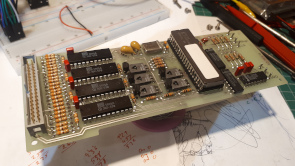
New 390R resistors soldered in place.
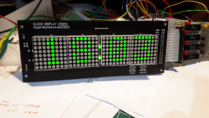
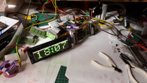
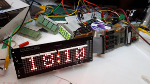
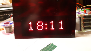
The new clock face under test, first green then red.
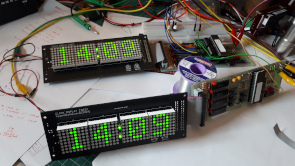
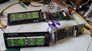
That's both clocks working, I just need to buy a few components to let me complete the project. The height of the Time Set switches wasn't known until the boards were built, and the pillar heights that'll hold and space the two boards and filter.
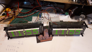
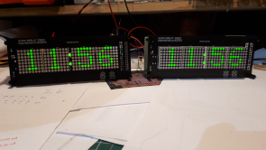
Using some pillars I had I cobbled together the two clocks so I could see roughly how they will look when complete and to free up some bench space for my next project..
I also moved the power supply from my bench unit onto a 5V 2A charger pack. The power consumption for a single clock with the old TD LED display is 2.5W, with the new larger display that falls to 800mW. That's them soak testing until the spacers and button arrive then I'll cut the filter, make a back plate for mounting and a long data cable.
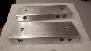
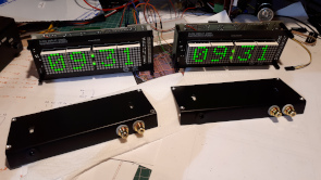
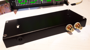
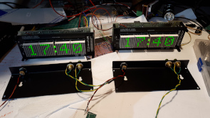
The clocks will be wall mounted so a back plate is required, this bracket has the 5V input and the data in & out terminals. I should really use twisted pair for the data but as I have plenty phono (RCA) connectors I decided to use them and coax cable.
I started wiring the mounting plates, the main clock on the left has two independent data outputs from the daughter board while the secondary display has a data loop through so I can easily chain another secondary clock.
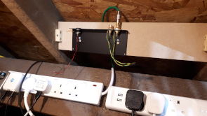
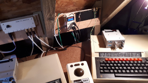
Readying the areas for wall mounting the clocks and running power and data cables.
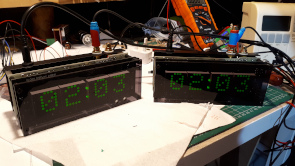
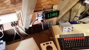
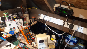
The clocks finally finished and mounted in position.
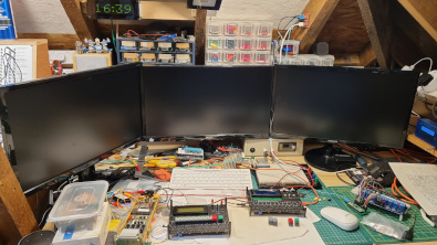
I realised that the two clocks were not mounted in easy sight of my Raspberry Pi desk so I built and mounted a third clock, a second secondary clock.
November 2025 - The Workshop Clocks were built in May 2021 and in only a few years use one pixel (LED) on the right hand display went dark..
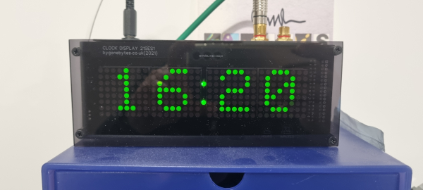
The easiest way to get it working again was to swap it onto the red LEDs, so one connector move and a link change later..
