A new Patchboard for the Maplin 5600 Synthesiser
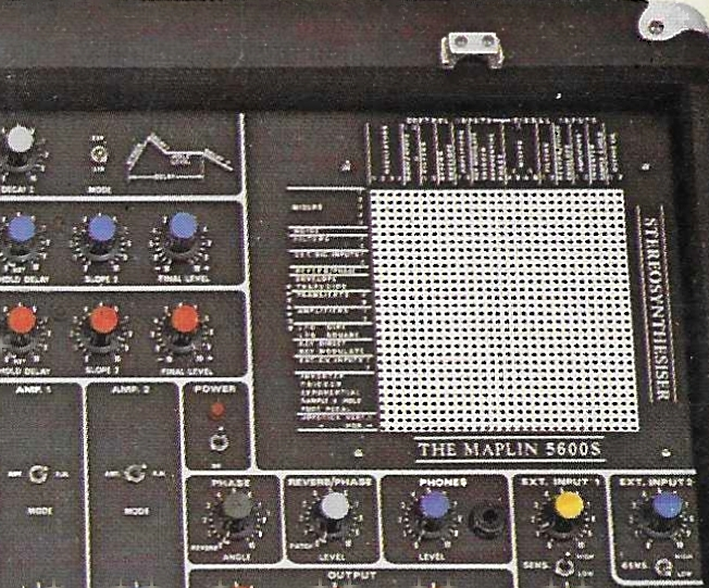 I received an email from another Maplin 5600 synthesiser enthusiast wondering if it was possible to make a software version of the patchboard. This is
something I considered at the beginning of my project (please read my page on the Maplin 5600) but dismissed it for a couple of reasons, 1) it would
require a ridiculous amount of bi-lateral switches (900), and 2) I didn't think I had the programming skills.
I received an email from another Maplin 5600 synthesiser enthusiast wondering if it was possible to make a software version of the patchboard. This is
something I considered at the beginning of my project (please read my page on the Maplin 5600) but dismissed it for a couple of reasons, 1) it would
require a ridiculous amount of bi-lateral switches (900), and 2) I didn't think I had the programming skills. I then learned about a single package 16x16 matrix switch which has all the controls, switches and latches on board. Now having just completed my RPi Pico 2 upgrade to my office clocks and had gained a bit of experience in building and creating serial data streams which this IC uses, I thought it might be possible for me to do something with it.
I downloaded the datasheet and did a rough calculation of cost for the final item. First looking up the price for an IC, the AD75019JPZ, from known good suppliers such as Farnell UK are about £50 each then there is a Raspberry Pi, the cheapest is probably the PI3A+ at £24 then there is a screen, £40 - £60 and finally the rest of the PCB and components, £20. A total of roughly £300.
I also looked at Aliexpress to see if the AD75019JPZ was any cheaper which they were at around £10 each. This is a great saving and if they work and are reliable will bring the cost down to about £140 which is much more realistic.
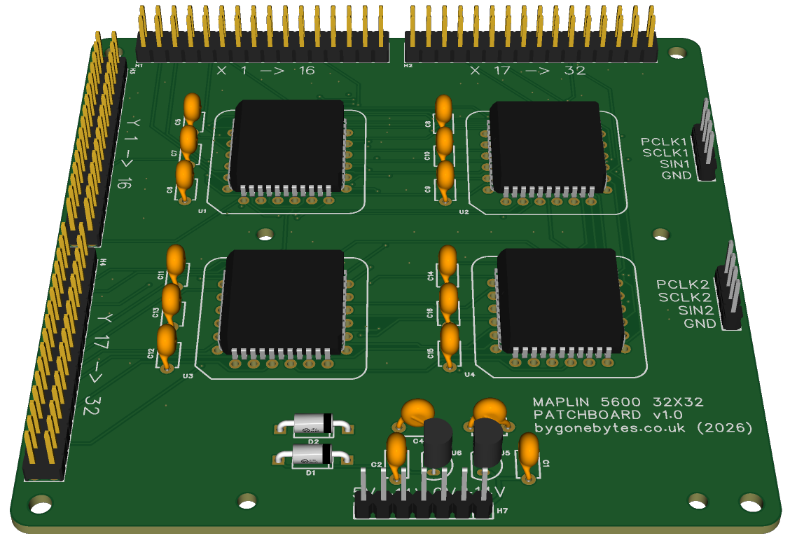
I placed an order for just two devices and set about designing a prototype PCB. The PCB had to have at least two matrix IC's so I can test casscading (passing the data through one device to the next), the I/O and control signals brought out to edge connectors. I also considered how it could be powered. The Maplin Synth has +/-14V and 5V available and the Matrix IC requires +/-12V and 5V so I added a couple regulators to reduce the 14V to 12V..we'll see how that works..
Before I started on the PCB I worked out the configuration of matrix IC's to make up the required 30x30 matrix (it'll actually be a 32x32 matrix) so I scribbled down what I thought might work and transferred that to EasyEDA.

I also had to consider how to build it, surface mount or through hole components. Surface mount might prevent some people from building their own but through hole could make it a larger circuit board. At the moment the board size works out to be 100x100mm but it will likely require a lot more space if I have to add buffering op-amps to the switch I/O. I will need to look through the Maplin circuits to see if this is required and if it does I'll need to use sixteen quad op-amps (I'll need to research to see if I can get more op-amps per package). Through hole versions may be better so they can be easily replaced as there may be at risk of some unwanted voltages being injected.
Anyway a prototype PCB has been ordered and should be with me in a couple of weeks.
The software
There are two parts to the software, the data transmission and the graphical interface. As I said above I programmed a RPi Pico to send serial data to some Train Describer display modules that I use as clocks. That data stream is very similar to what is required for the Matrix IC, Data and a Clock. The Matrix IC requires the data to be sent and latched at a minimum clock rate of 20KHz as the shift registers are dynamic and the data would fade if it was any slower. The RPi Pico GPIO using Micro Python could barely reach 30KHz, I suspect the RPi3A would be much faster but I thought I'd look for a more reliable way to send the matrix data. So I asked AI! (first time for everything) and it pointed me in the direction of the SPI interface and the spidev library. This should get the data transfer rate up to 1Mhz, equivalent to approximately 1ms to send the entire 1024 bits which will make the system very responsive. 1024 bits as I will casscade all four Matrix IC's, each requiring 256 bits.
The graphical interface - I have built a few of these in the past, my sequencer (Python 2.7) and my Midi keyboard (Python 3)..Which one I'll base it on I haven't decided yet.
It would be nice to be able to have a screen that fits and replaces the original patchboard (120mmx120mm) but that may be tricky to find, it also needs to have a resolution that can display a 32x32 button grid clearly on the screen without scrolling and you can touch without interferring with adjacent patches. I think I'll need to do some experimentation to see how everything could fit.
Other ideas are the possibilty of saving and loading patches but that's for further into the future.
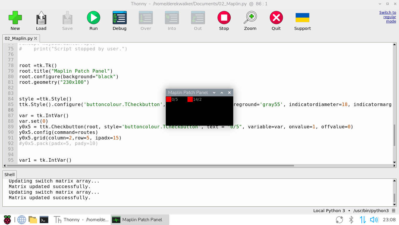
First steps with the graphical interface, I've made a small window with just two buttons for testing the new PCB. If that is successful I'll scale it up to 16x16 matrix then on to the full 32x32. Colours may change..
The prototype PCB arrived so I built it up with the power supply regulators and one AD75019 socket. I checked that the power supply voltages were correct and on the correct pins of the matrix IC.
Adding the IC I tested the switch with my small test program and then with a 2 row, 16 column version.
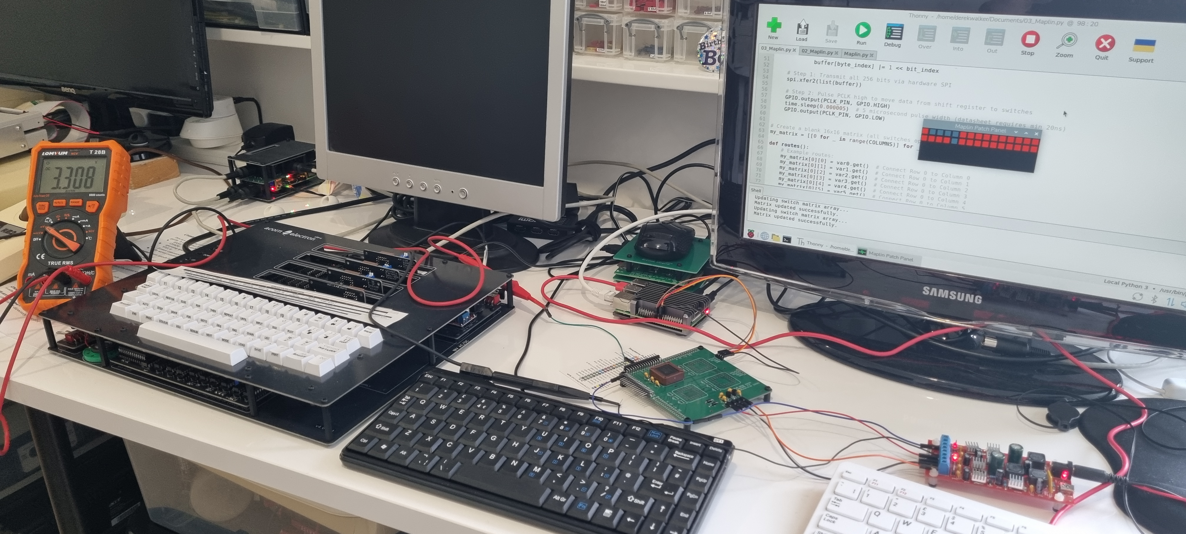
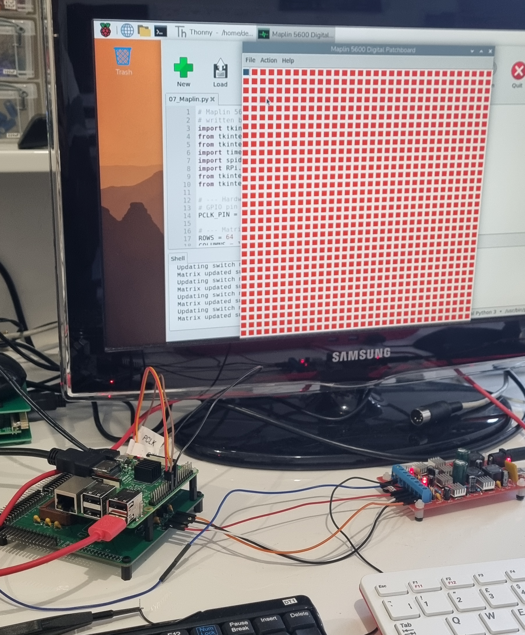
Amongst my untidy desk is the prototype board connected a temporary power supply and a Raspberry Pi 4. I set up 3.3V flying lead to test each input with my multimeter measuring the output. The screen shows the 2x16 test matrix display.
Next is to alter the test program to a 2 x 32 matrix so I can test the data cascading ..
And that is done!
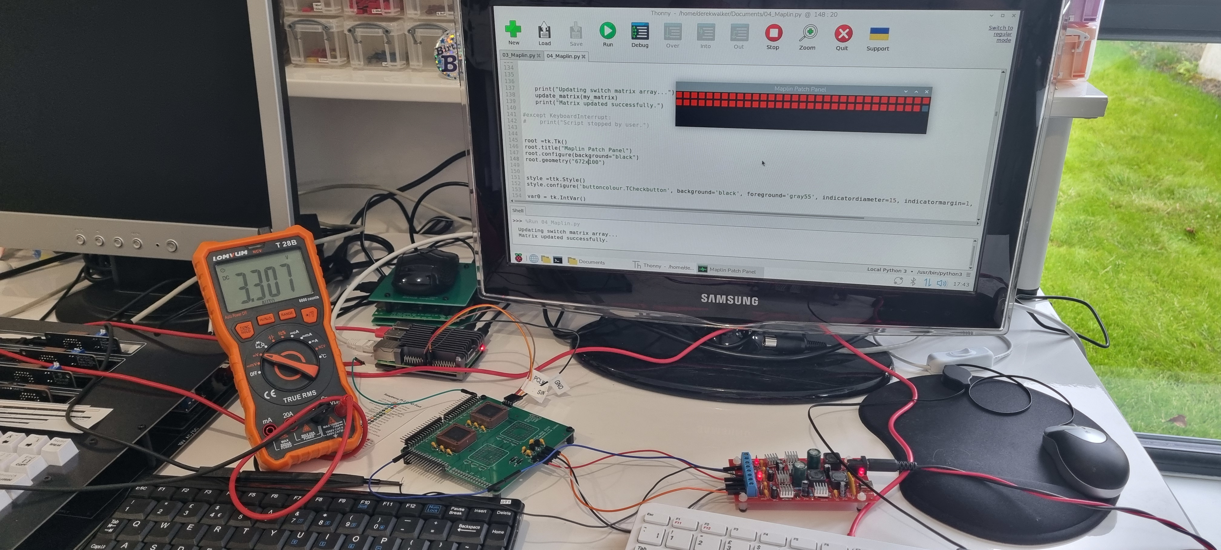
A lot of work still to do..that is only 64 buttons, the full array is 1024 buttons - a lot of copy & paste and editing..
I also have to redesign the PCB to include op-amp buffers - 16 quad op-amps! At the moment I have changed the through-hole decoupling capacitors to surface mount as it saves a lot of space but I have kept the op-amps as through-hole so they can be put in sockets for serviceability.
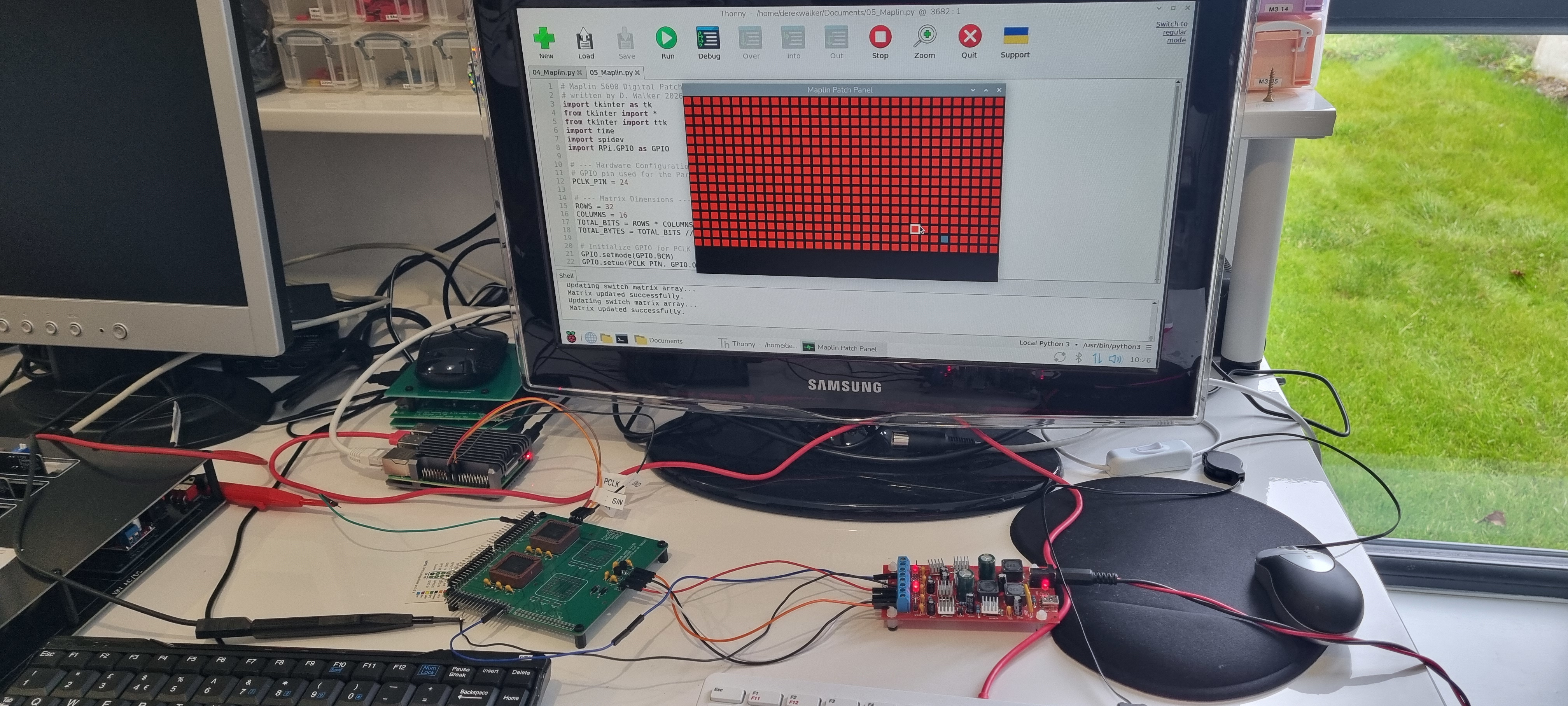
The first 512 buttons programmed and tested. That's all I'm going to do with this prototype board, I'll be concentrating on the next board to get it ordered. Once that's in production I'll use the two week wait for the delivery to bring the program up to the full 1024 buttons.
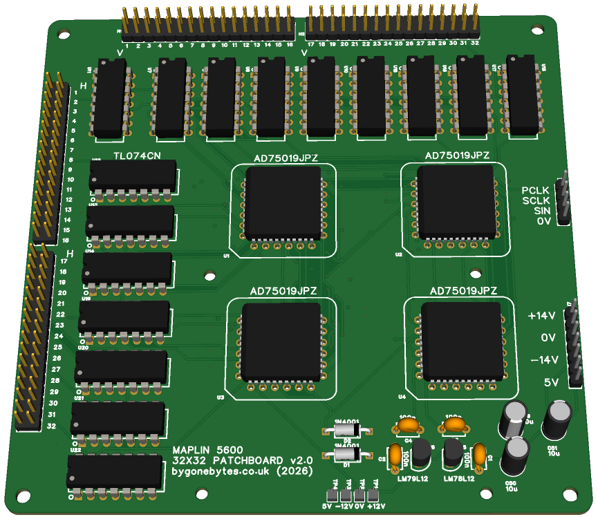
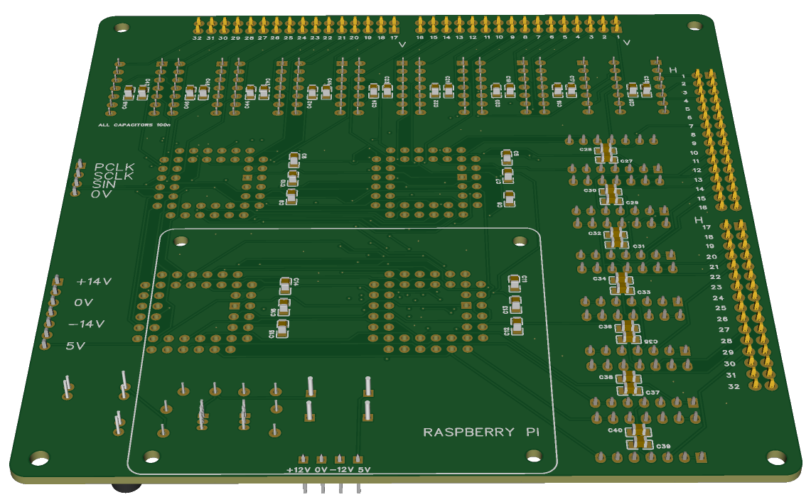
I increased the PCB from 100x100mm to 120x120mm to allow for the op-amp buffers. The matrix switches on the prototype board were bi-directional but now with the buffer IC's they become directional - the signals go into the H1-32 and V1-32 are the outputs from the matrix to the synth control and signal inputs, it's easy to get mixed up here!
With the Vertical buffers in place I am now thinking about the difference between open circuit (hi impedance) as in the original pin matrix compared to the 0V outputs from these buffers - what effect it will have on any of the input circuits. Maybe output buffers is not the way to go..we'll see.
Back to the software..
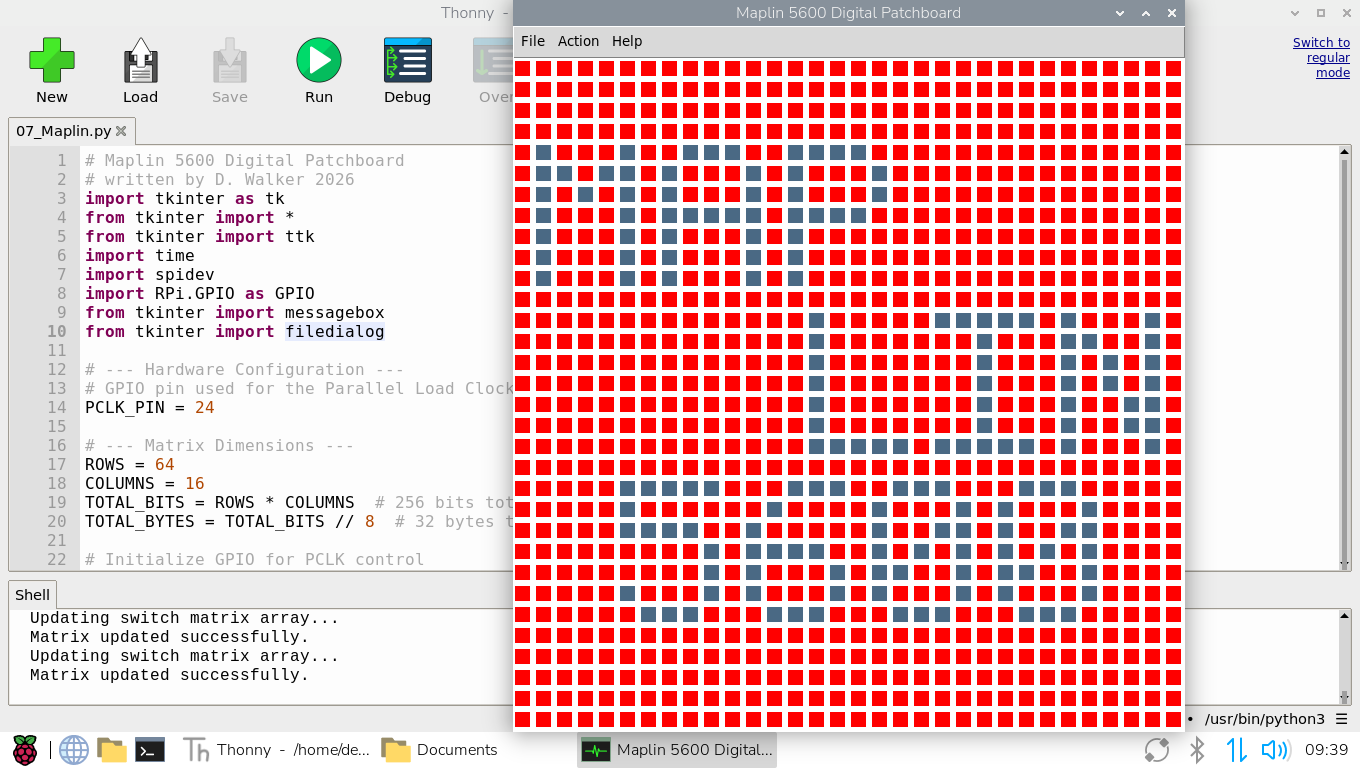
This is my first full program. It has a 32x32 grid of pins, only a 30x30 grid is required for the synth but the new patchboard hardware is capable of a bit more so I've included the extra rows/columns for now. I've added options to save/load patches and to clear all pins.
I still have to consider labelling if any.. I could colour code either the columns or the rows to make it easier to locate patch points.
Which Raspberry Pi to use..
When I built the sequencer in 2018 (8 years ago) the Pi 3A+ and 3B+ were the top of the product line so my choice then was the 3A+ basically because it was the lite version at a lower price. Now of course there are a few more options including the Pi 4, 5 and the Pi Zero 2.
This program is probably the 'heaviest' I've written as it has to track over a thousand variables so I thought I'd see how it runs on a range of Raspberry Pi's.
The Pi's I tried are the Zero 2, 3B, 3B+, 4 and 5. It run successfully on all of them but responsiveness varies in the same order.
The Pi Zero 2 was the slowest at starting the program at 11 seconds but once loaded it performed the same at the 3B and 3B+. I used the patch screen above (an unrealistic and complex patch) to load and clear and these three Pi's all took about 4 seconds to load. The 3B and 3B+ took around 8 seconds to start the program. The Pi 4 would start the program in 3 seconds and 2 seconds to load the patch. The Pi 5 starts in less than a second and loads the patch in under 2 seconds. Just clicking a Pin is as good as 'instant on' for all them so any of these computers would do the job, for me the choice will be down to the easiest to passively cool.
From these results I still think the Pi3A+ would be the best option, it takes less power than the 3B's, 4 and 5 and therefore it'll run a lot cooler and at just £24, affordable. No heatsink required. I have just been reading that the 3A+ production was due to stop in January 2026 but has been extended until January 2030, what would be ideal is a Pi4A or 5A with 1 or 2Gb ram - I would have thought at least a 4A would have materialised in the last six or seven years!.
I just looked at the price of the Pi4 I was using and it is a staggering £158! so I've packed that away for use on another project.. the prices are a bit high for the Pi4 and 5 to be recommended. At the moment I don't have a 3A+ so I am going to recycle my 3B+ from my now defunct Pi-Top laptop so here it is running happily with just a tiny heatsink.
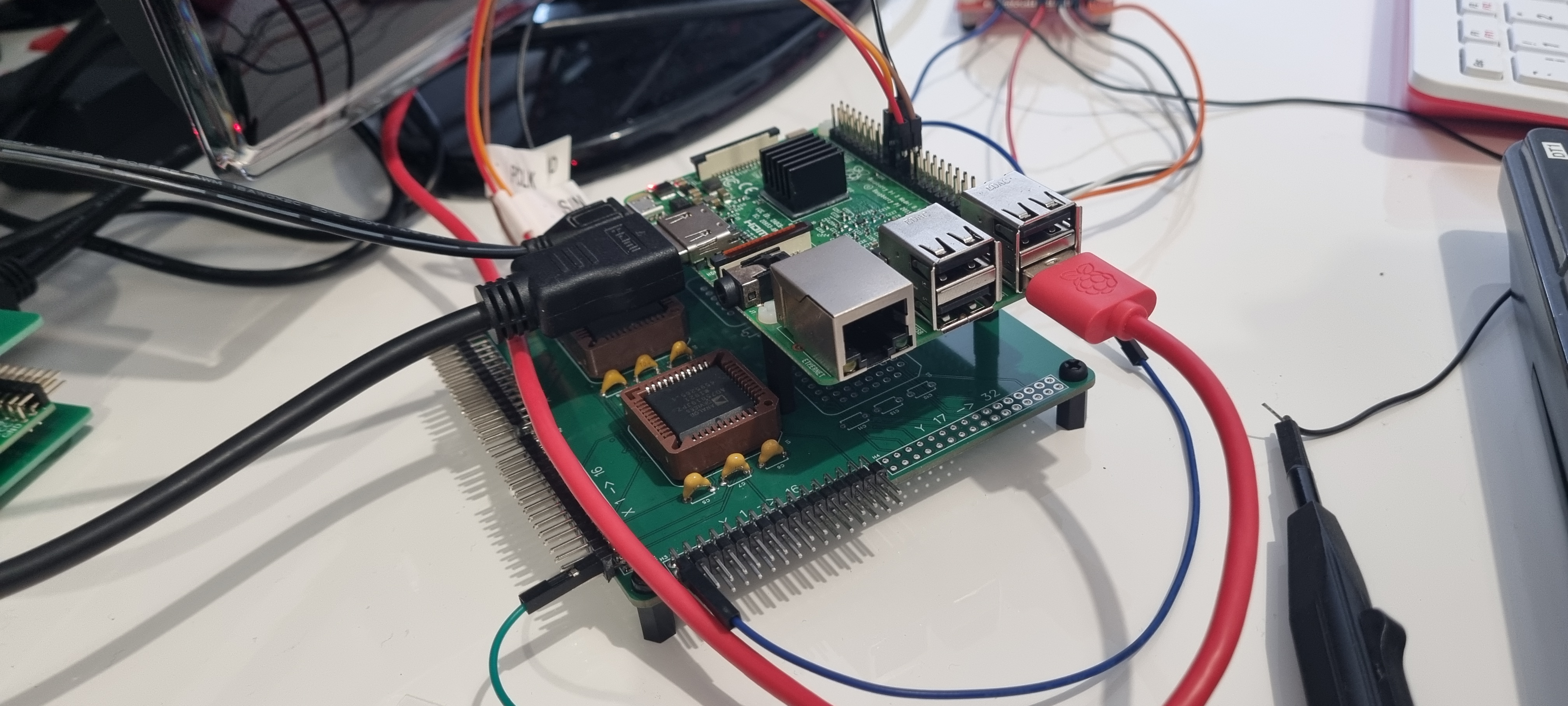
And a few days later I have a P3A+ to try. Even with just 512MB of RAM the timings match the 3B+ but it runs 5 degrees cooler at 28 Degrees C with no heatsink so I'm happy with that.
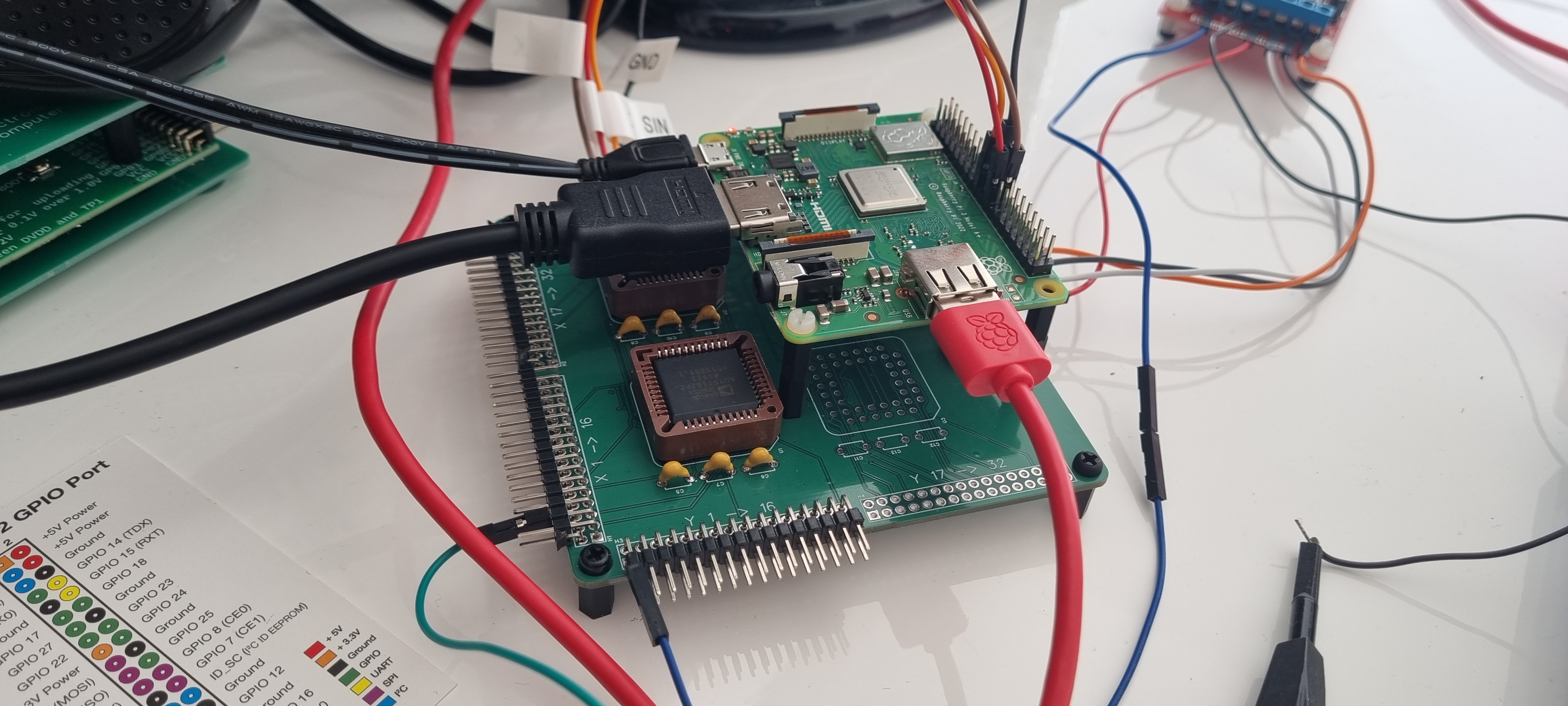
And a few more days later.. I have completely re-assessed the above. Whilst using a RPi3A+ I noticed if I opened a second program, file manager for instance, it would slow down to a halt. Not very practical! I then tried the RPI3B+ and it was a bit better but it was very jerky when moving a window so a RPi4 is the minimum I would recommend. I am now using a RPi4 2GB model and it's very smooth and responsive.
Which screen to use..
I have an old Raspberry Pi 7" that I use for a midi keyboard which I thought would be interesting to try with the new program. The minimum window size for the matrix is 672w x 736h but this display is only 800x480 so I know it won't fit but I thought I'd give it a go anyway...
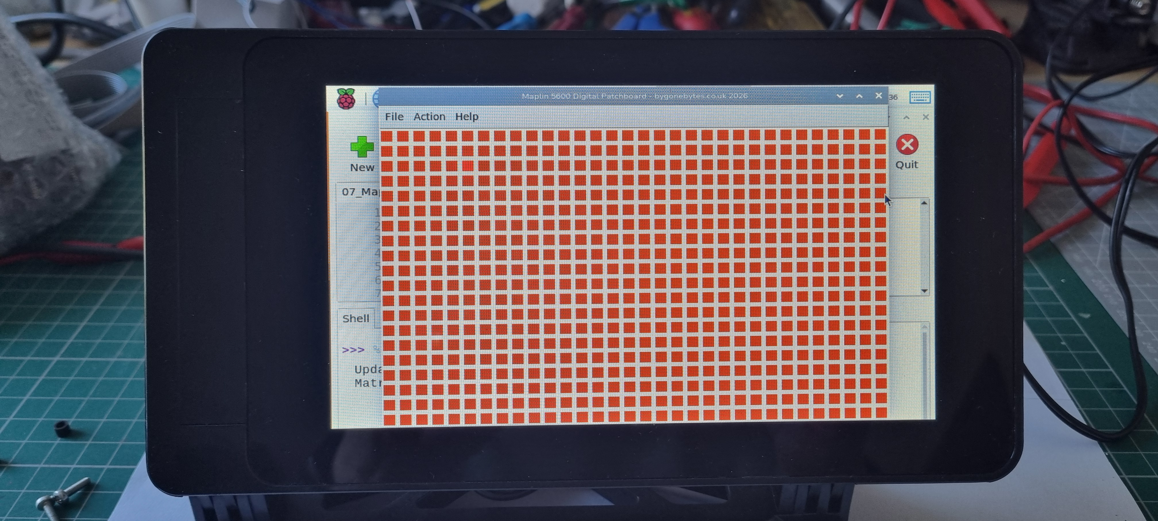
As expected it only shows the first twenty rows on screen..anyway onto something that should work. Pi Hut has a Waveshare 8" 800x1280 DSI touch display that is 119h x 194w, this should do nicely.
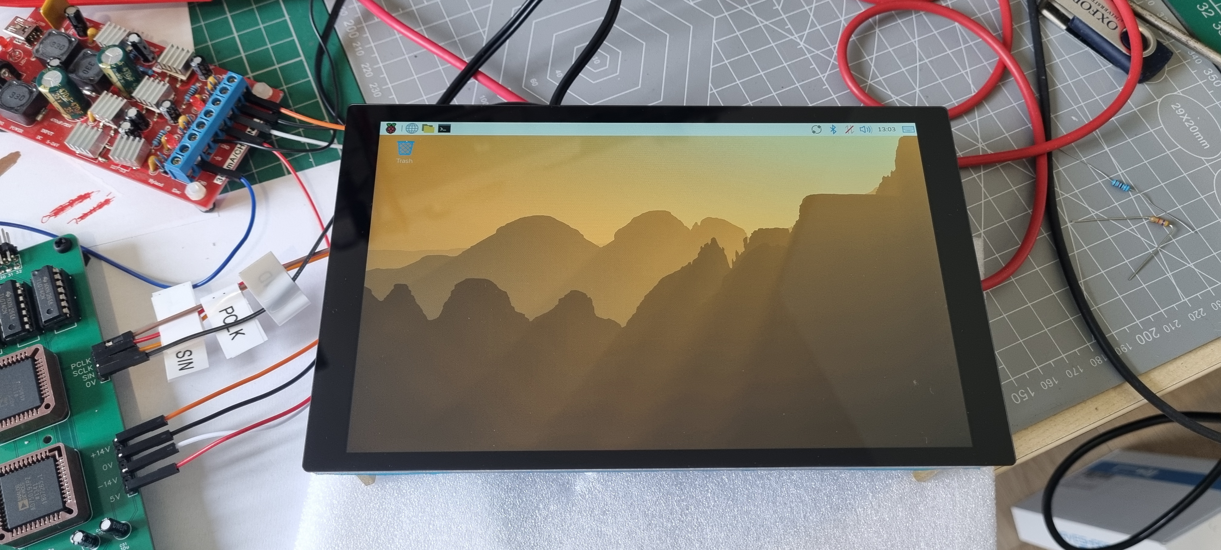
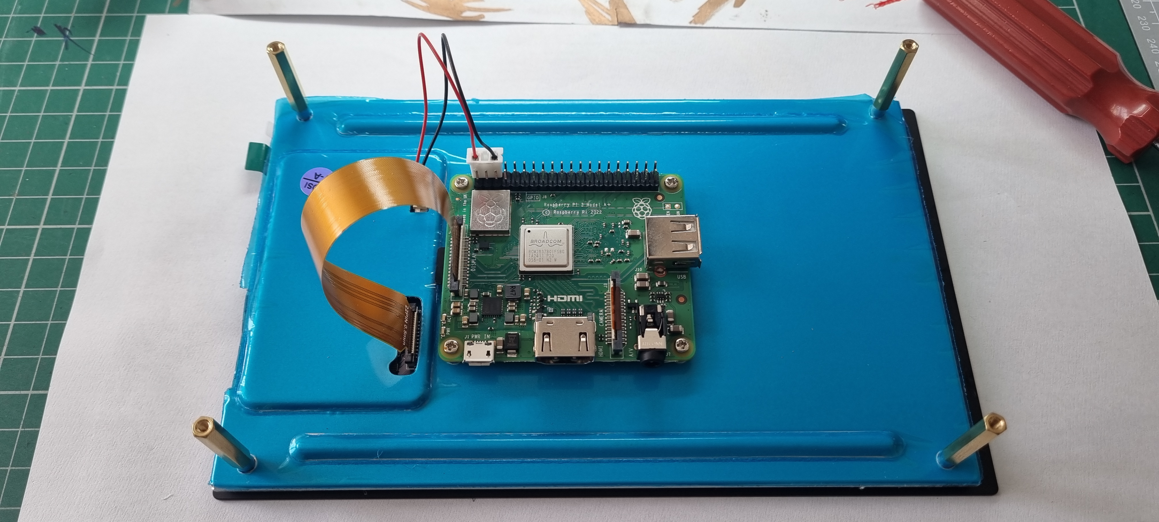
And the RPi fits neatly on the back.
The button matrix will fit the display in either orientation, here's a couple of screenshots..
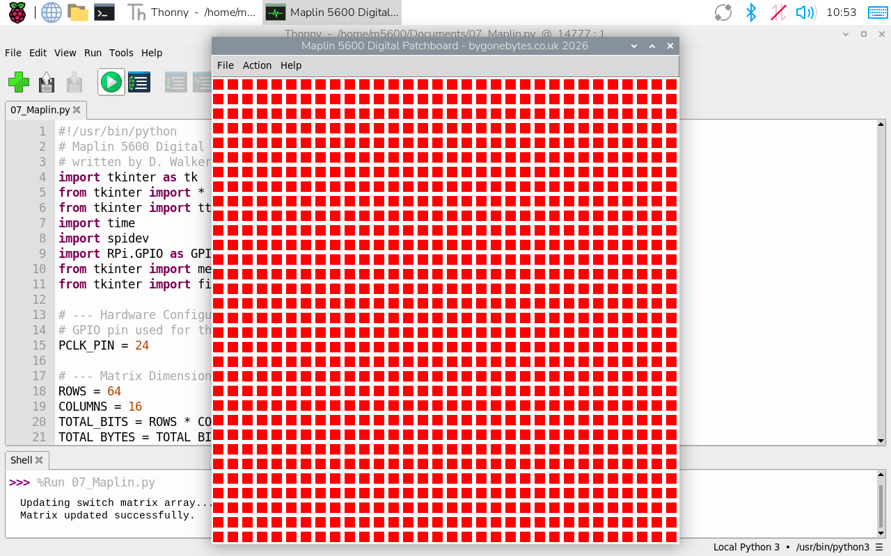
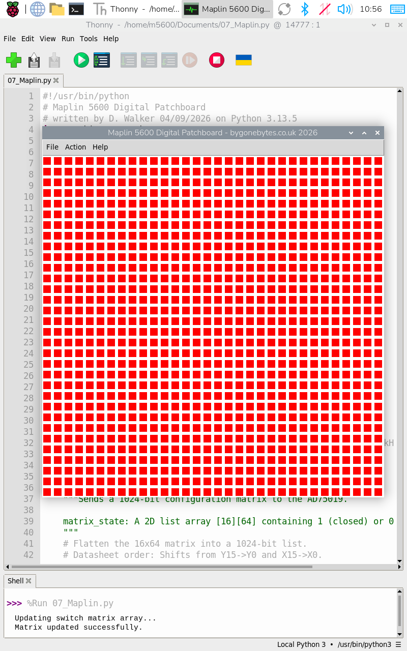
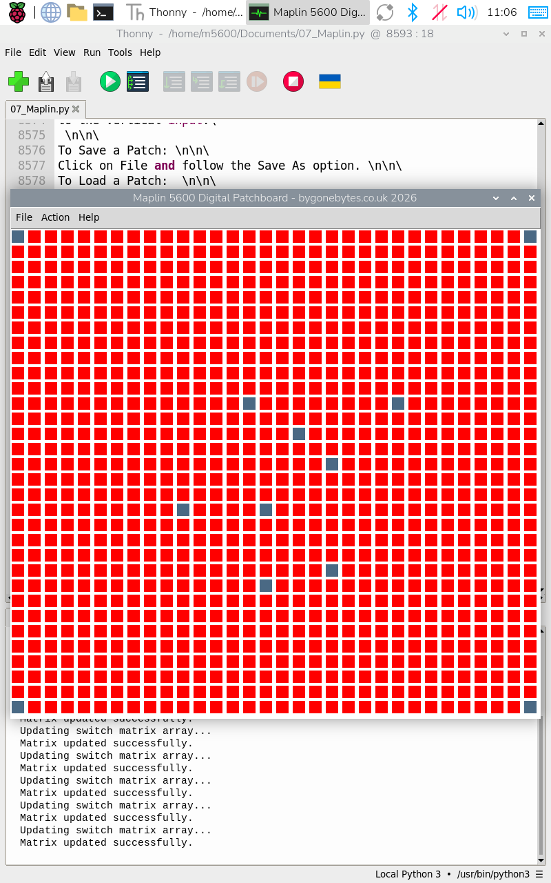
There is space to make the buttons a bit larger, the photo above right shows them enlarged which will make it easier to touch a Pin.
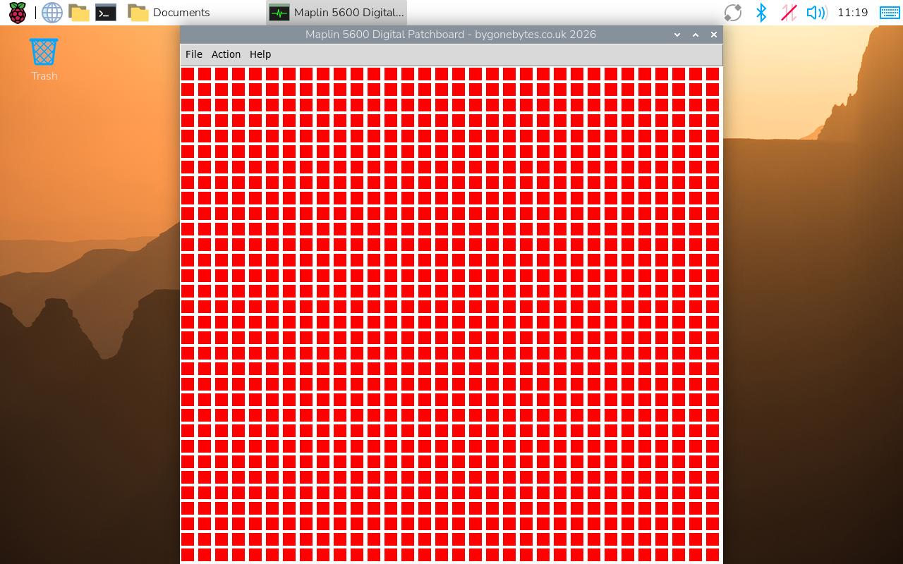
The program running without the Thonny Editor, I just need to create an icon for it.
Back to the PCB, the first full board built and assembled ready for testing.
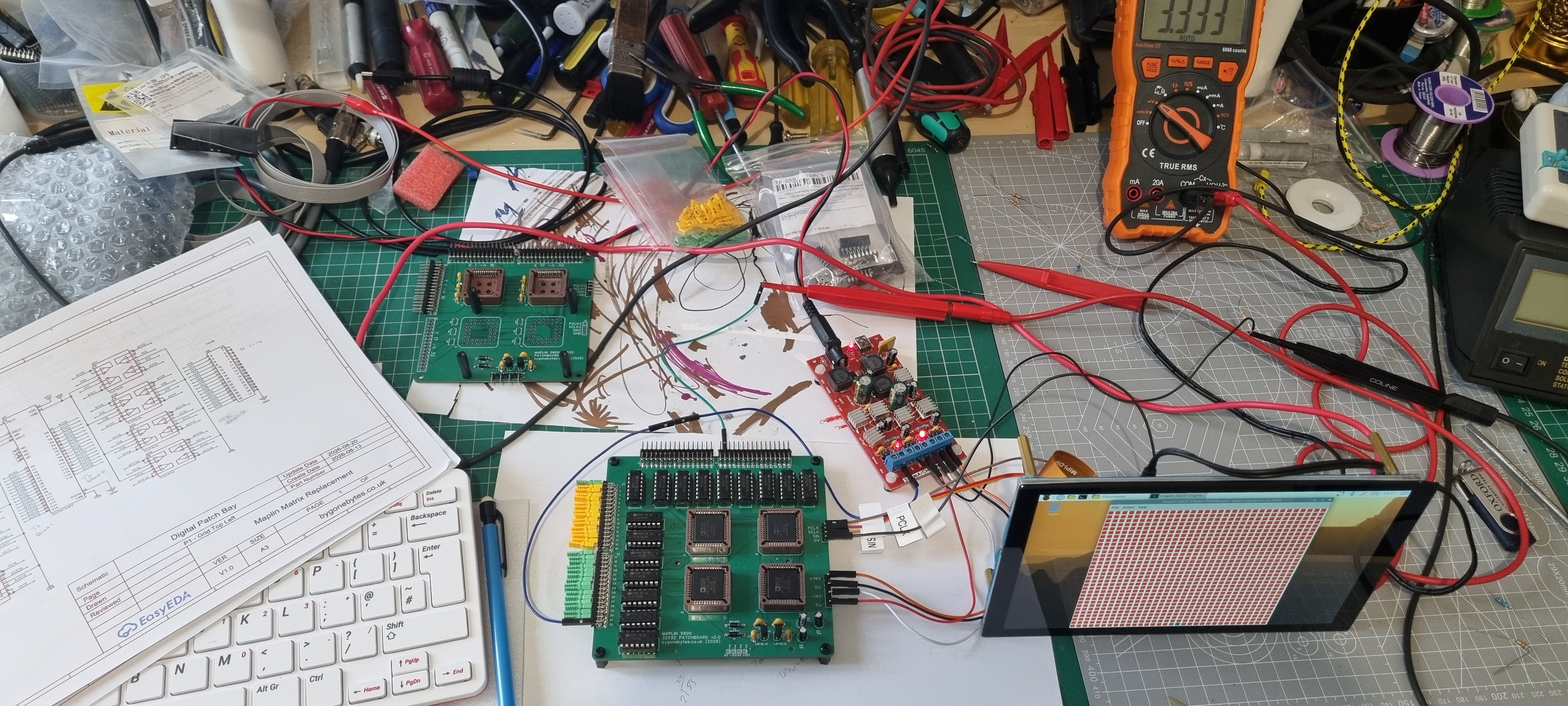
And it works great except for...
I know the TL074 inputs are high impedance which I considered with respect to the Horrizontal Inputs and I knew the synthesiser output circuits would terminate them but what I missed was the output from the matrix IC's to the Vertical buffers and what would happen when the switches are off - of course they float high..arrgh. These inputs all need a pull down resistor - thirty two resisters! another board is required...
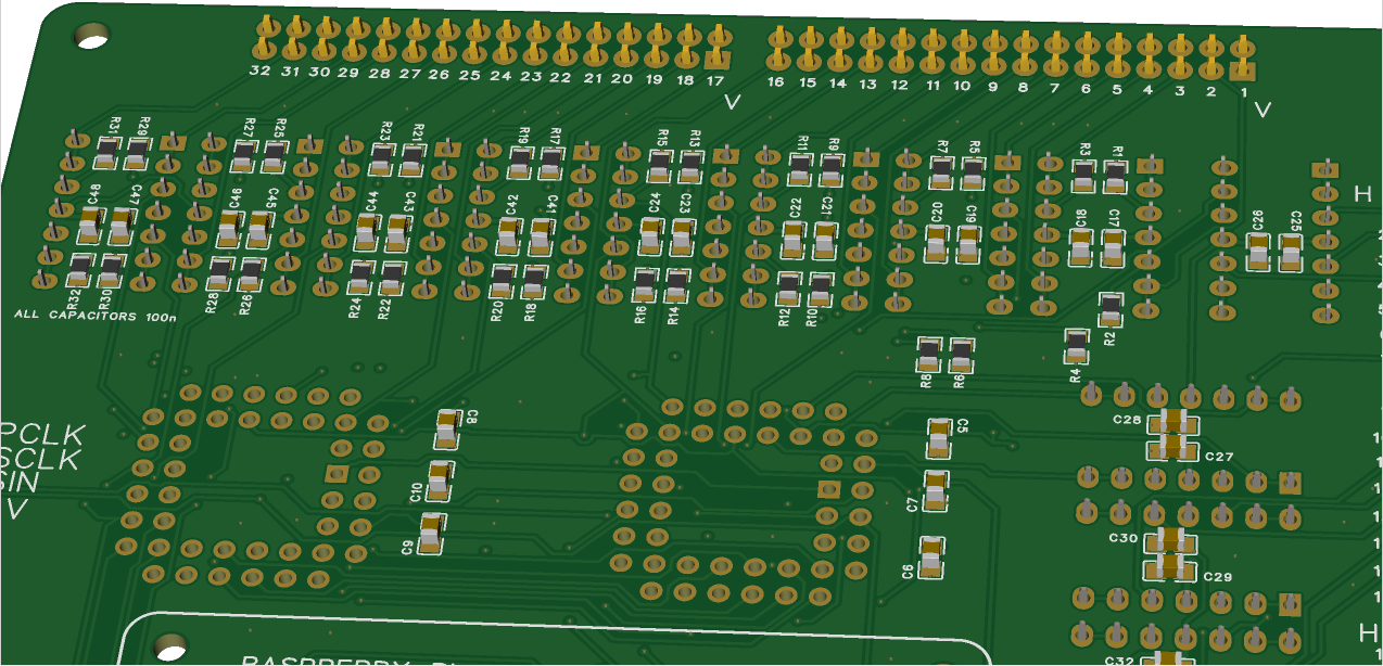
Thirty two resistors added to the underside.
Added an Icon, so just a double click to start. When I'm finished I'll make the program auto start from power on.
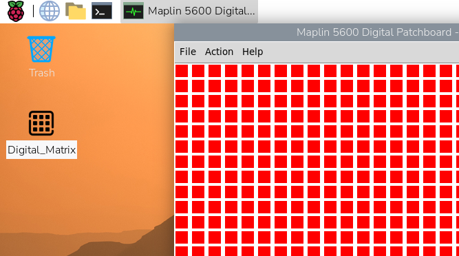
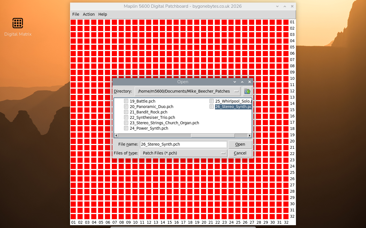
I have been creating patch files for the sounds/effects that appear in Mike Beecher's How to Play the 3800/5600s booklet which gave me a feel of using the patchboard. What come out of this exercise was I need to add reference points on the grid. I tried making every fifth row a different colour but it didn't look right so I took some inspiration from Mike Beechers book and added row and column numbers. There wasn't enough space to add descriptive labels.
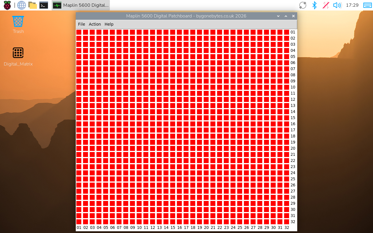
A couple of updates, Raspberry Pi updated their OS a couple of days ago and made some welcome changes. To make space for a decent window size I usually use the taskbar autohide but that has been missing from the OS for a while but this update not only returns this feature but also includes the option of a dock menu. I have implemented this and it enables me to make the pins a bit bigger and gives a nice clear screen layout.
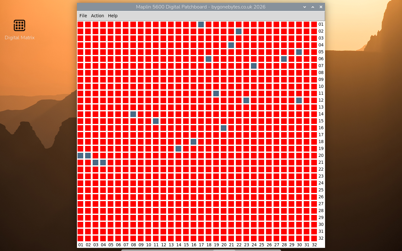
and as mentioned above I fitted the RPi4 2GB to the back of the screen. It just runs so smoothly now. I have ordered a heatsink that can be bolted on to ensure it is secure..this one could fall off at any moment!
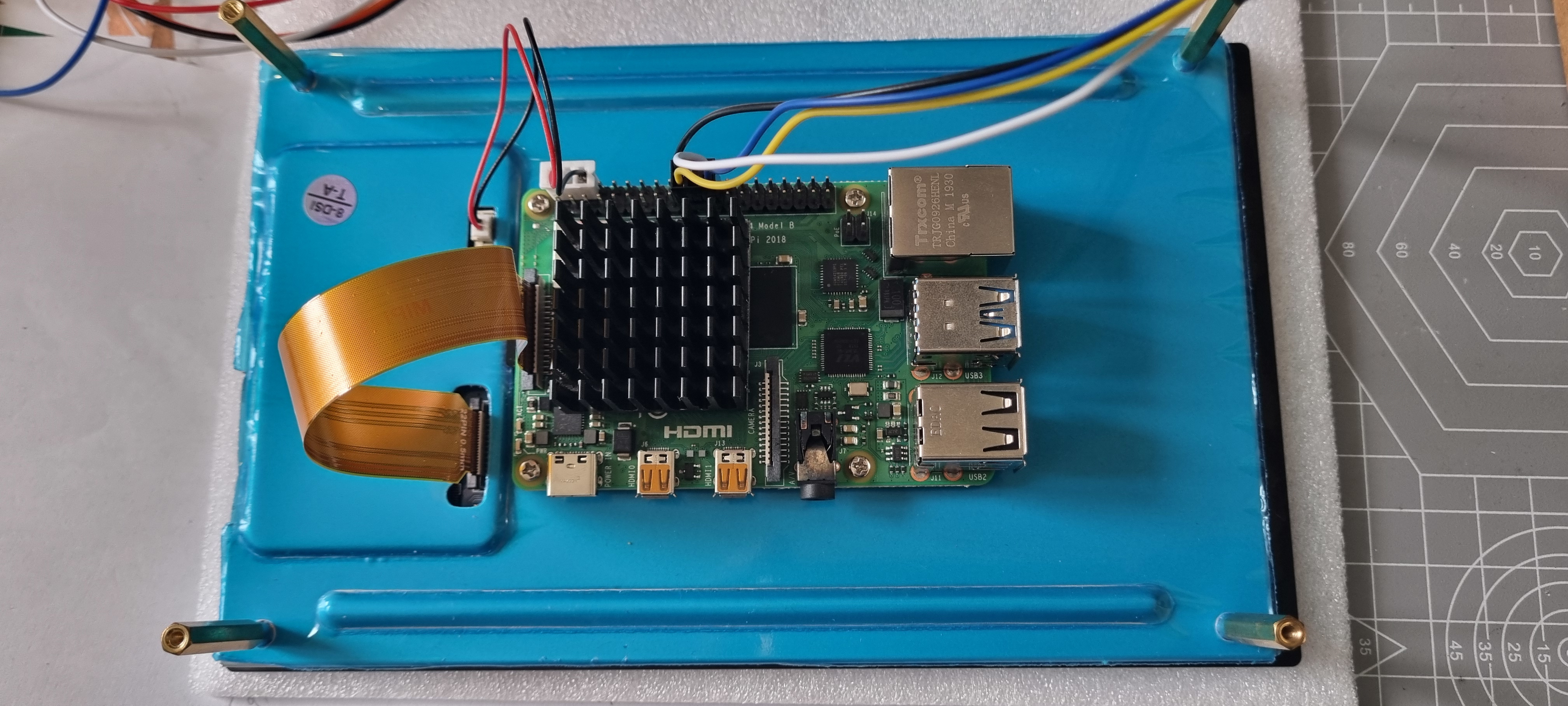
Something else I need to consider - from the start I intended to mount the Raspberry Pi and the Matrix board together but when I got the screen it was evident that the Pi and the screen need to be together due to the short ribbon cable between them.
This will probably mean the Matrix board will be remote from the Pi/Screen combination so there will be a need to transmit the data between them over a cable maybe about 50cm in length. I have been using 18cm wires for testing and the 3.3V from the Pi has been 100% reliable but with the need to lengthen them I thought I should try a longer cable. At 50cm it was intermittent so I'll need to buffer the signals.
I will make a small HAT for the Pi with a 74HCT244 or a 74HCT125 which will lift the signals to 5V and hopefully that should get the transmission beyond 50cm.
Another curiosity, how the touch screen works. There are two modes, mouse emulation and multi-touch. Mouse emulation lets you double tap the icon to start the Matrix program but it doesn't work as expected when using the menus in the program. For example tapping 'File' opens the menu but if you tap an entry it does nothing. To get it to action a menu item I had to tap and hold 'File' and drag my finger down to the required entry then release. Not very intuitive!
Multi-touch enables single tapping on the menu items.. that's great but it disables icon double tap! The ethos of muti-touch (and now on the new dock in RPI OS) is single tapping on everything so how do I get around this? As it turns out very simple - open File Manager and edit preference to enable 'open on single click'. So with multi-touch and single click enabled it is very intuitive to use.
A little more progress..
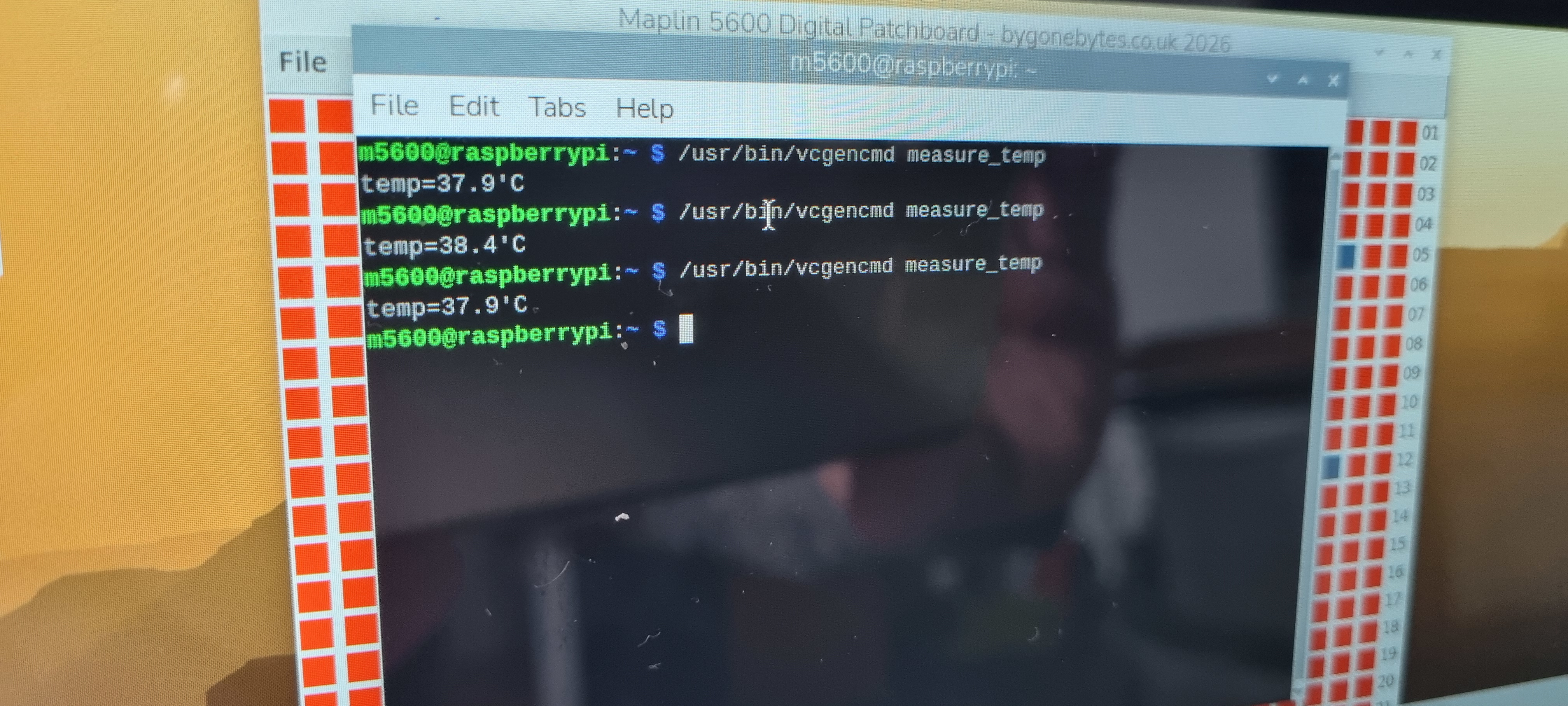
The heatsink for the Pi4 is now fitted, I chosen the Geekworm P165-B 11mm Embedded Armour heatsink. I fits neatly on top and keeps the processor temperature to a cool 38 Degrees.
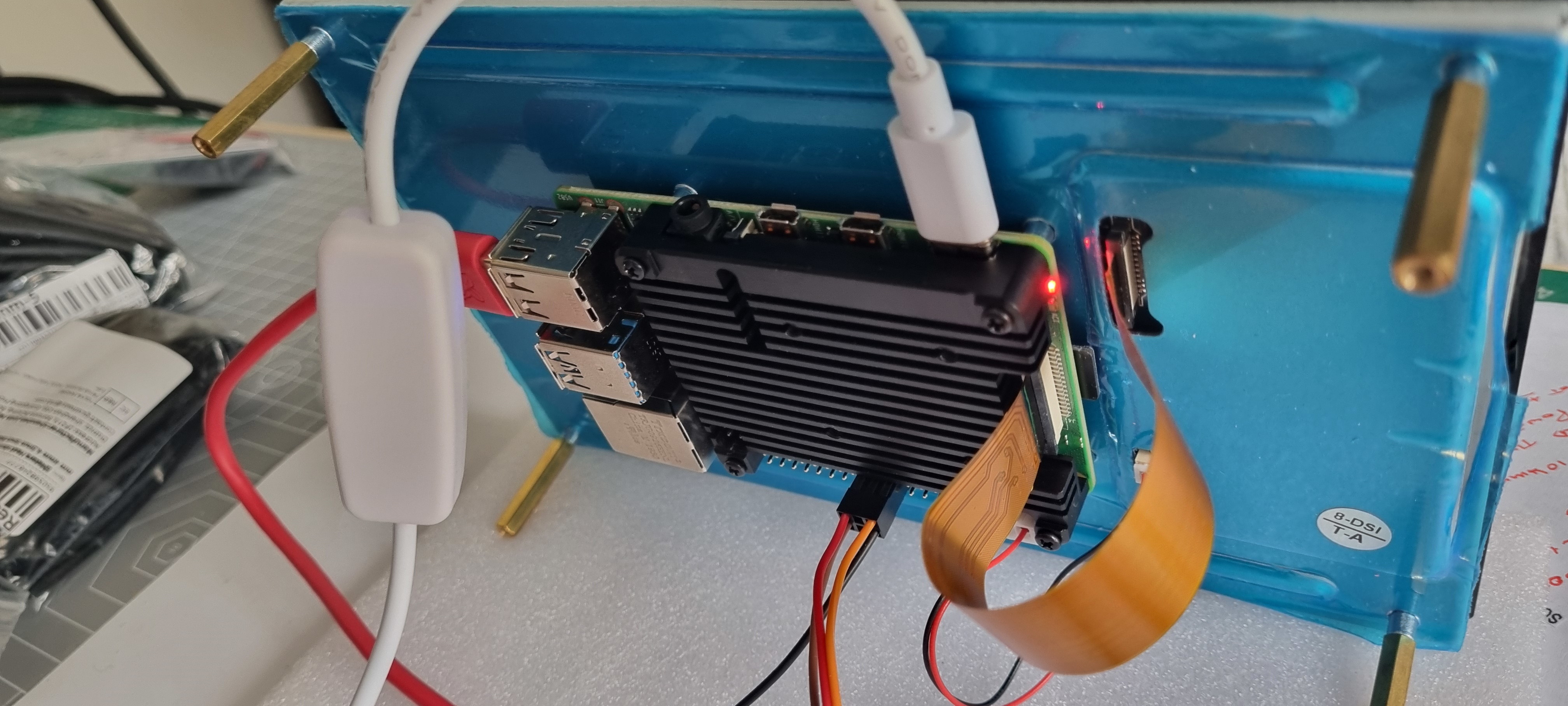
I've look out my Synth again and used a few boxes to set the monitor and circuit board on. This is the new v2.1 PCB with the pull down resistors added, everything works as expected now and is ready for a functional test.
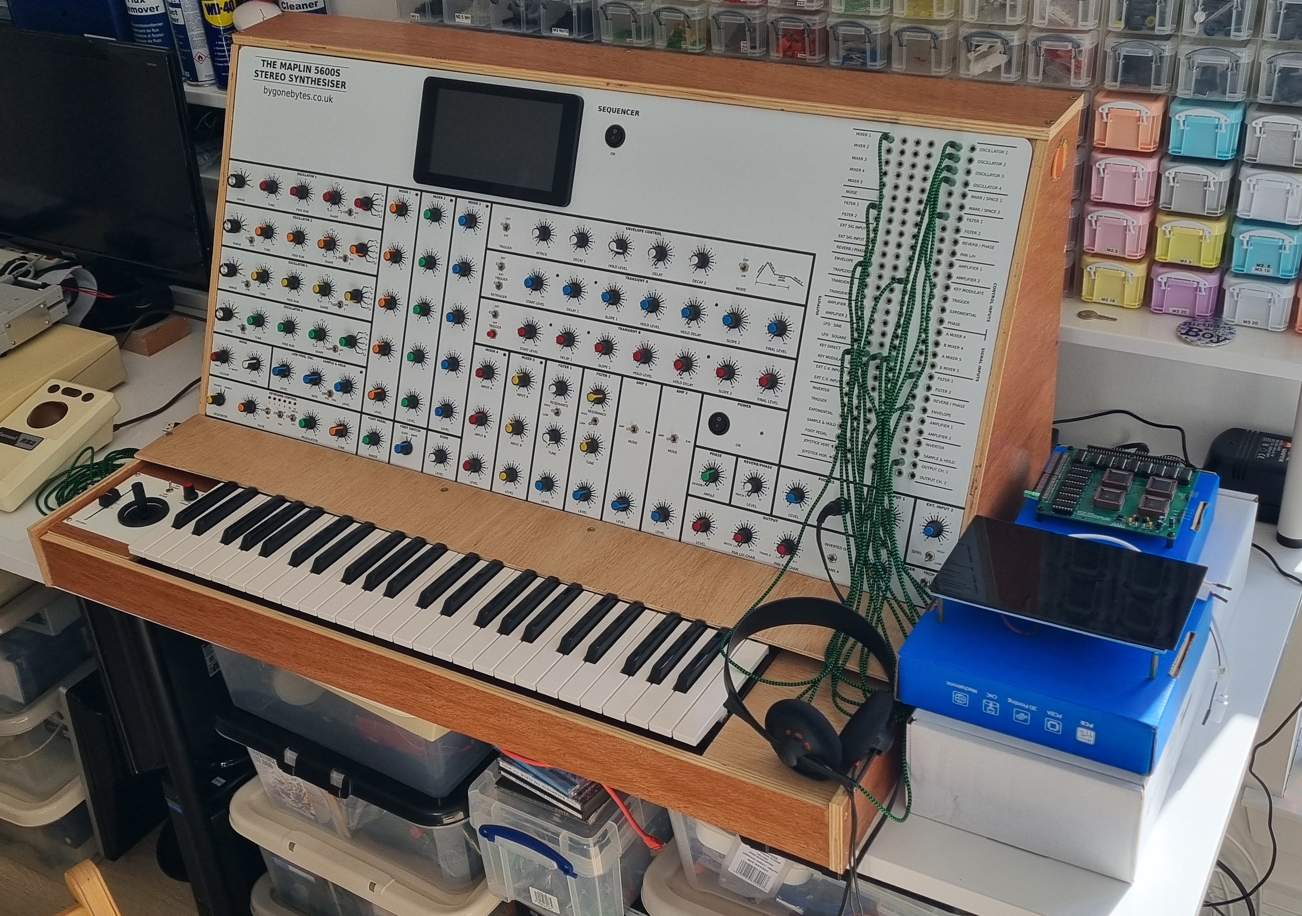
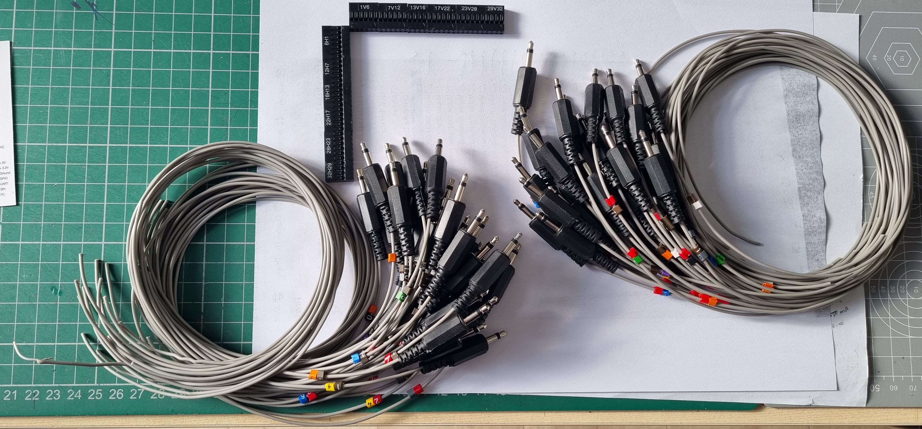
At this stage I don't want to be striping out my synth so what I'm going to do is build a harness that plugs into the front of my 3.5mm jack patch area. Having the PCB and monitor on the outside of the synth will make it easy for any measurements. The harness so far..I'm just waiting on some black hookup wire so I can terminate the cable screens.
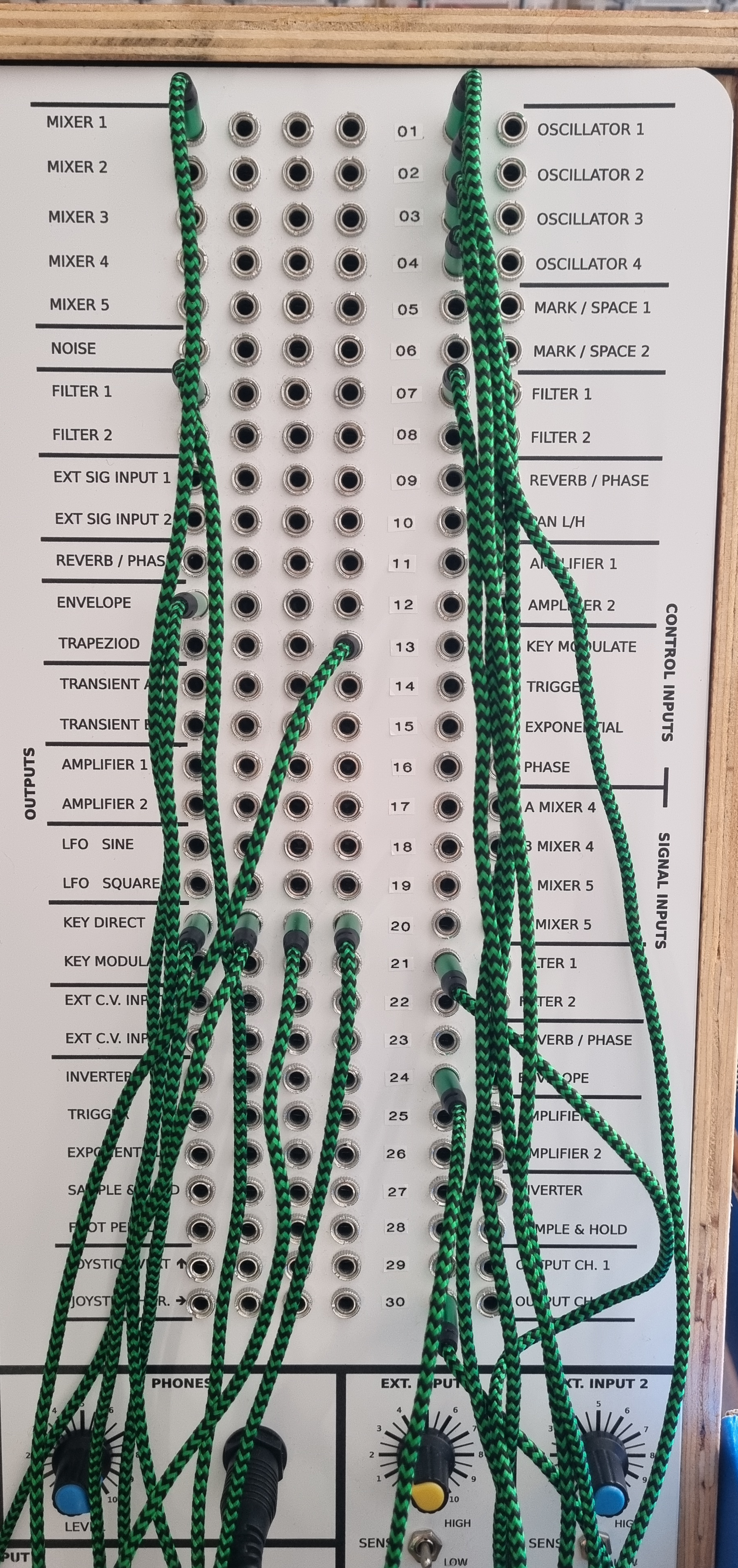
Idle hands..I added numbering between the patch I/O for easy cross reference to the digital patch.
Getting power for the matrix: Looking at the specification of the Maplin PSU it can only supply +/- 300mA at 14V, it may not be enough for this addition but I thought I'd try to see if it could cope with the extra load. I made up a power cable and changed the connector on the matrix pcb to accept the heavier guage wire.
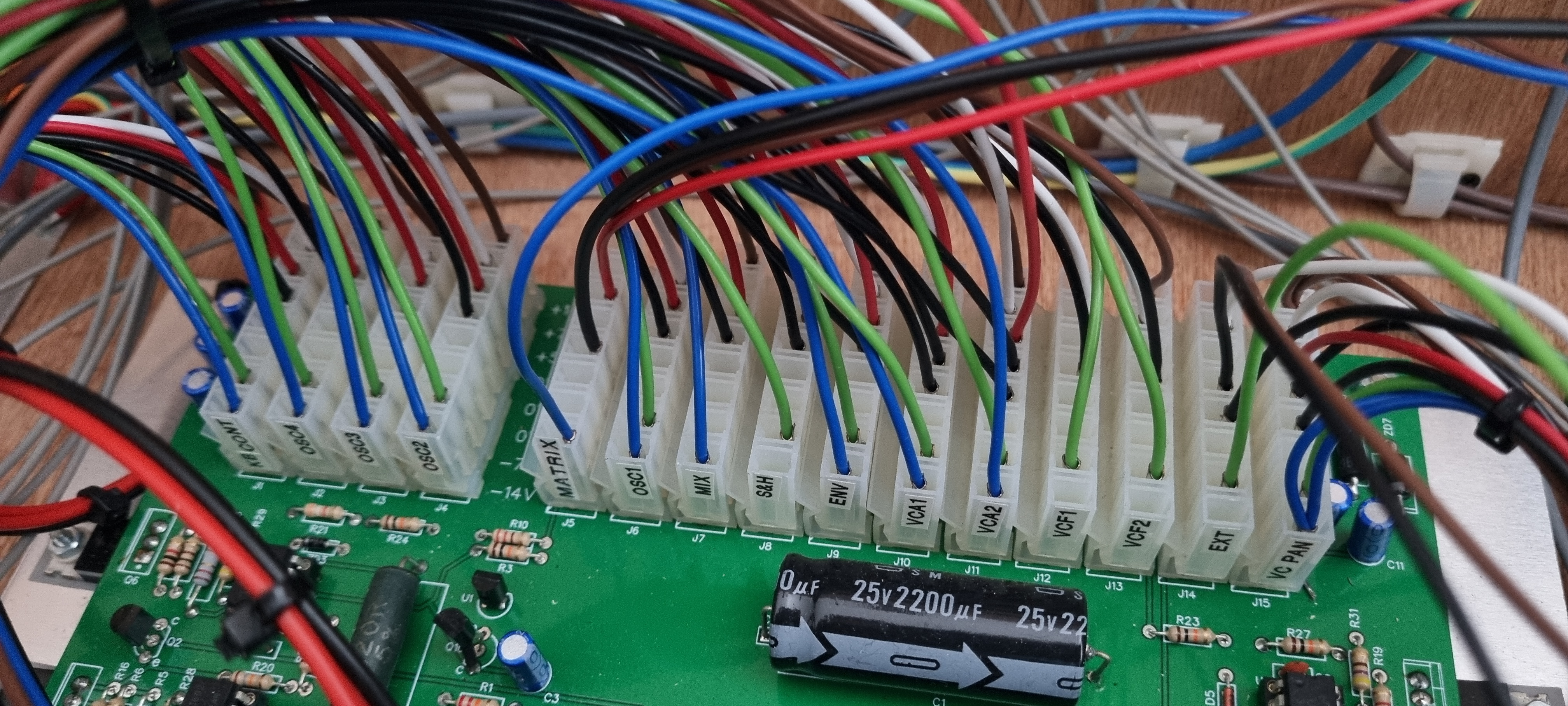
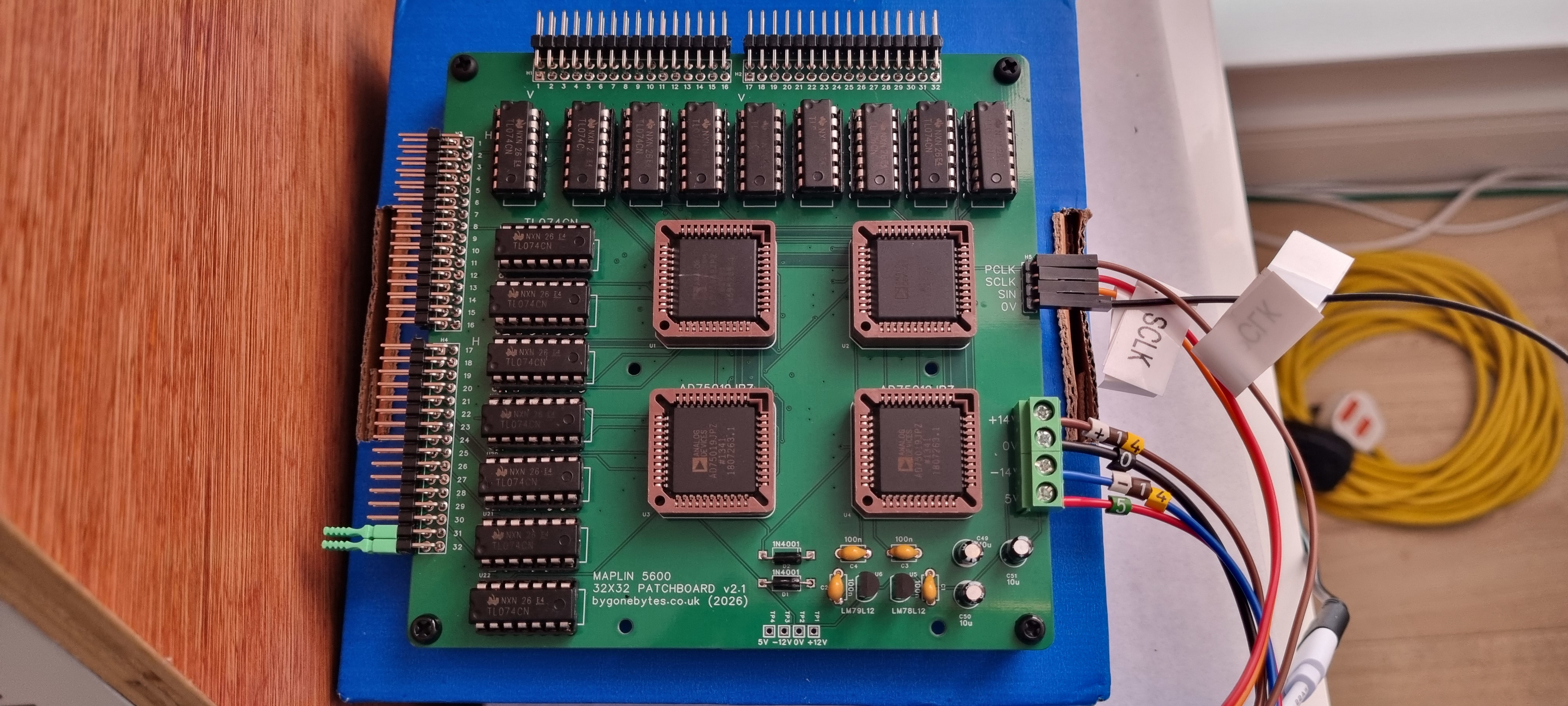
I switched it on and off a few times and the PSU held up so I thought it might be ok. I continued to connect all the Horrizonal and Vertical cables and switched on and the PSU keeled over.
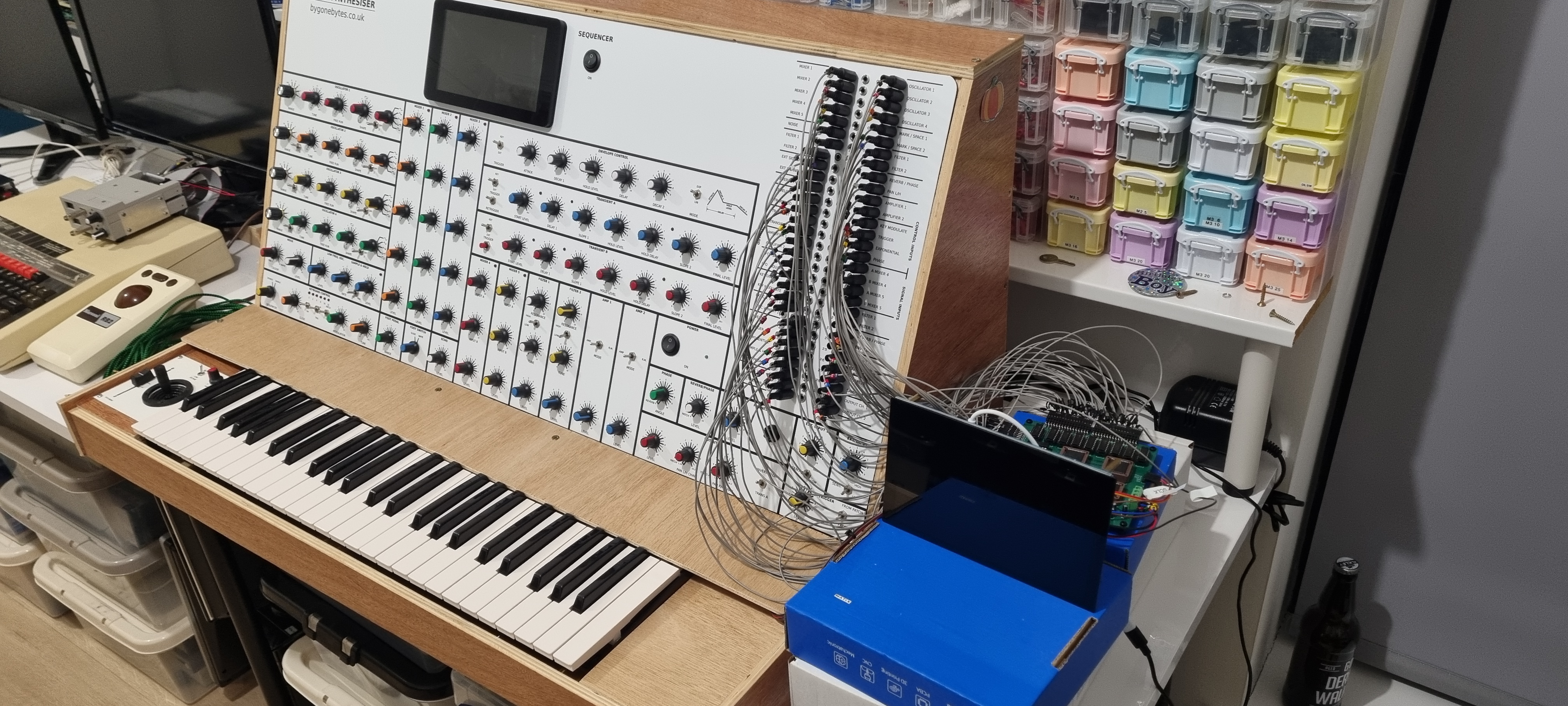
Not to worry, I reconnected my test PSU and I was all set to carry on testing.
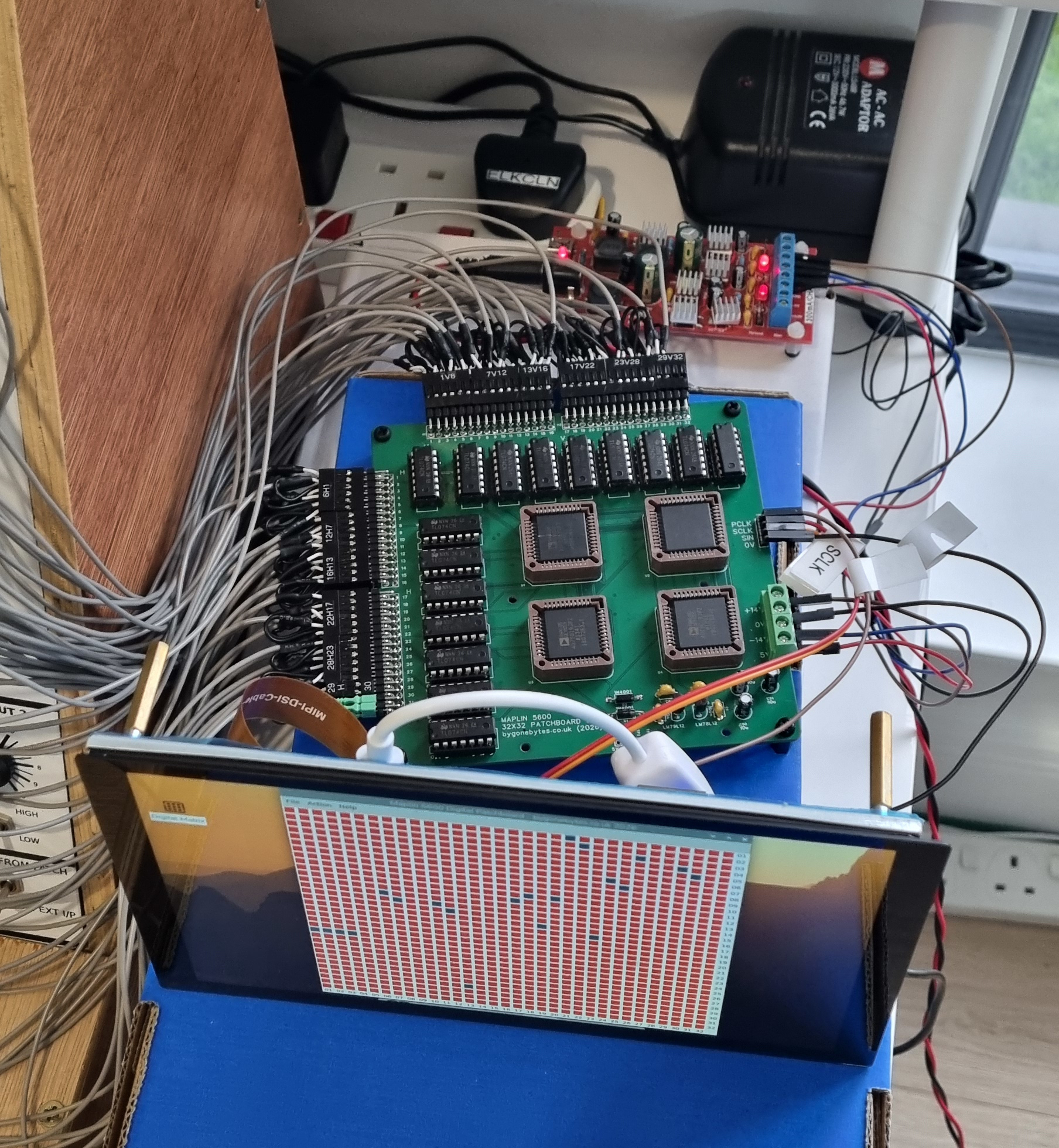
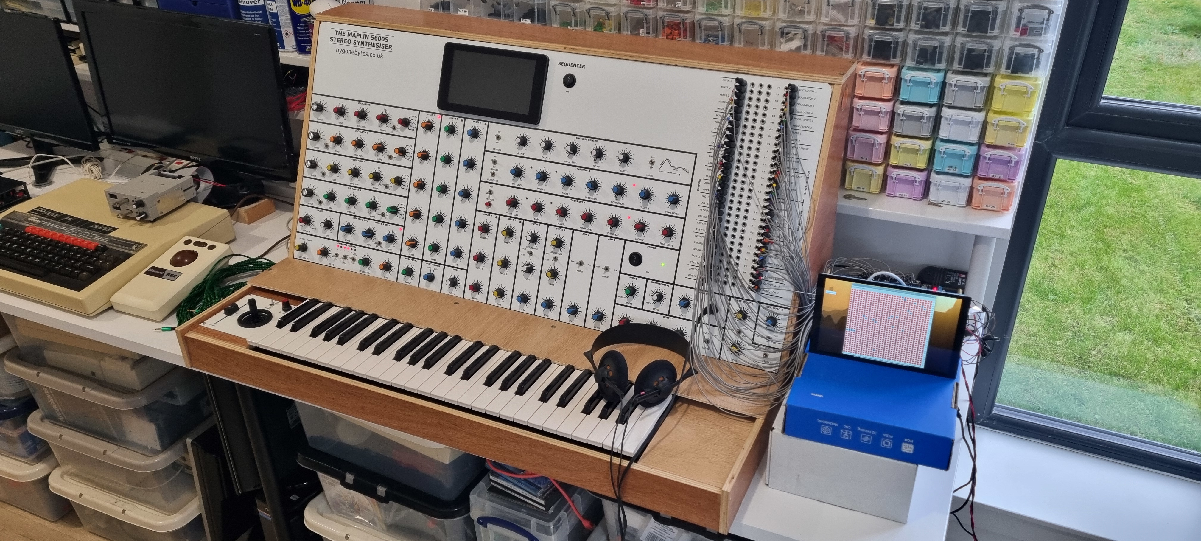
The first day the testing went quite well with only few things to look into. The second day went down hill very quickly. The voltages of matrix power supply were being pull down due to to much current being drawn. Back on the bench and it's working perfectly so I tried to recreate issue by removing some of the input links I use to stop the inputs from floating high. It didn't take long for the op-amp buffer to heat up and draw a fair amount of current. So an unterminated input causes the op-amps to drive a lot of power. I believe that over night some of the crimp connections went open circuit causing the power supply problems. I shouldn't have relied on the synth to termininate the op-amp inputs so I'll need to add resistors on these thirty two inputs.
When the matrix board tried to draw more power than the small 100mA regulators could cope with they also got very hot. I'll need to upgrade these to 1A versions to mitigate any chance of them overheating however the matrix only draws +/- 20-50mA under normal use.
I also found I could hear through the data being clocked into the matrix through my headphone, it's just a short zip sound and only happens when there is a change to the matrix but enough to be annoying. I need to add another set of resistors and capacitors to try and filter out this noise.
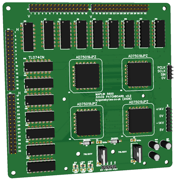
Since another PCB is needed I'll take the opportunity to add some LED's so I can see at a glance the status of each power rail. I'm also looking into the power block that will power the screen, Pi4 and the matrix board..there's a few options I've found which I will test out later..
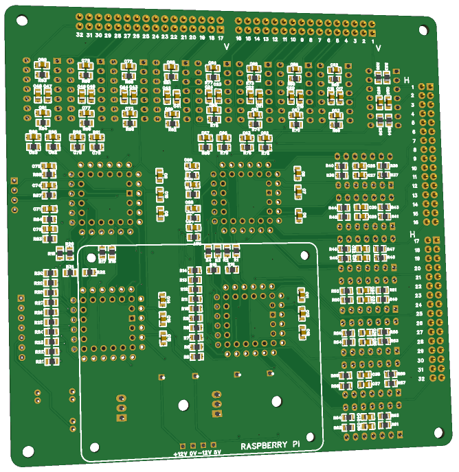
There will be a total of 67 new resistors, 32 new capacitors, two replaced regulators and I've changed the remaing through-hole capacitors to suface mount. I will use the 'belt and braces' technique and cut off all the crimp connectors from the patch cables that I spent so much time making and solder them directly to the matrix board so I don't run into these issues again.
v2.2 of the board with the changes..
waiting again..