Circuit migration from EasyEDA Standard Edition to EasyEDA Pro
Here I am again migrating designs from an earlier version of schematic capture software. I have been using EasyEDA Standard Edition since 2016, it was a good fit with what I wanted to do at the time, producing small simple designs ready for fabrication. A few years later EasyEDA introduced the Pro version and at that time it was far too advanced for what I needed so I basically ignored it.
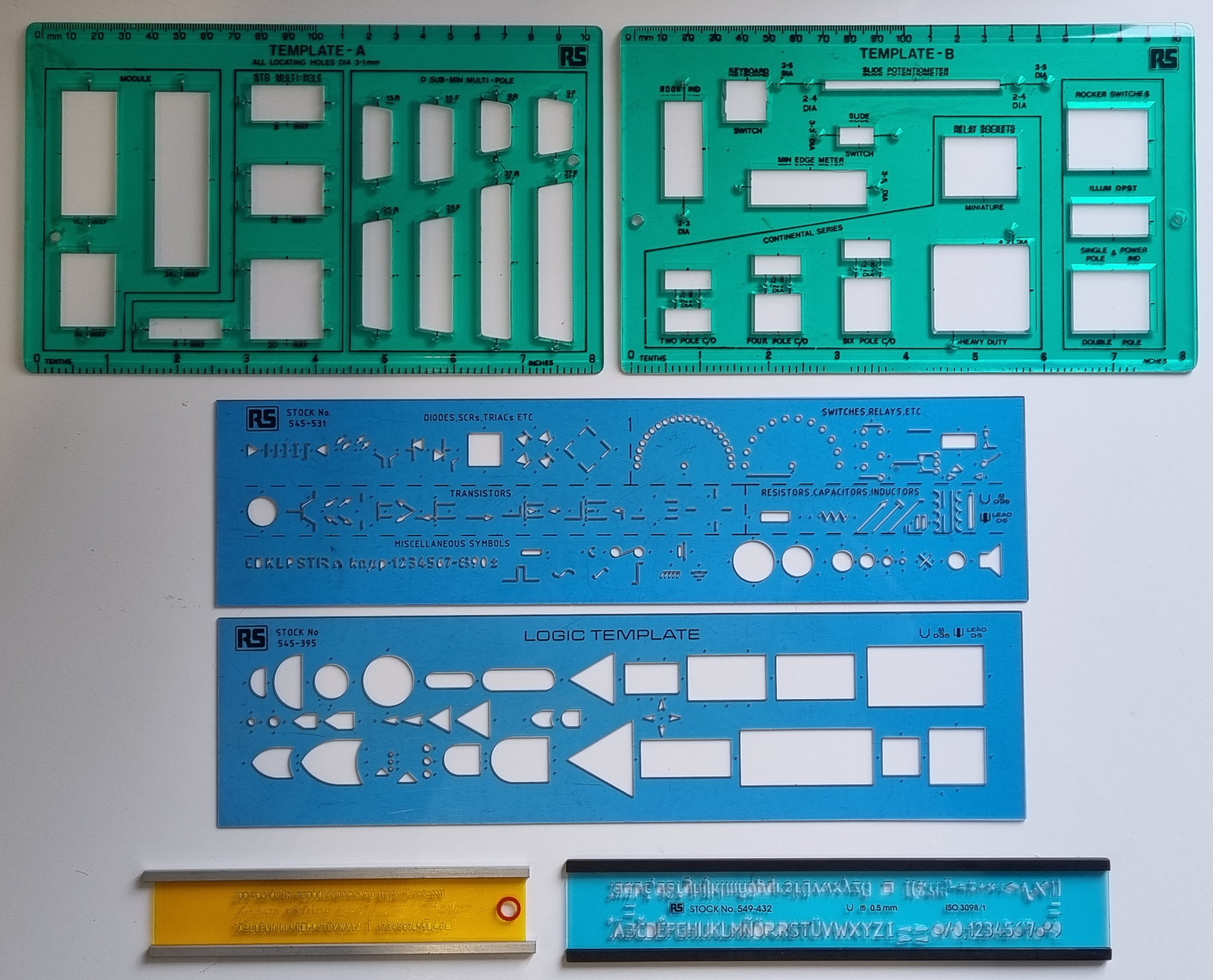
Now I have to take notice as the standard version is being phased out or at least not being kept up to date. Change is not new..back in the early 1980's I designed using pencil and paper. I used the stencils pictured below to draw diagrams..

By the mid 1980's designs got more complex so it was justified to invest in a 386 PC, a schematic capure program, Orcad V3/V4 and a HP Pen Plotter. This made a huge difference in time and quality of output.
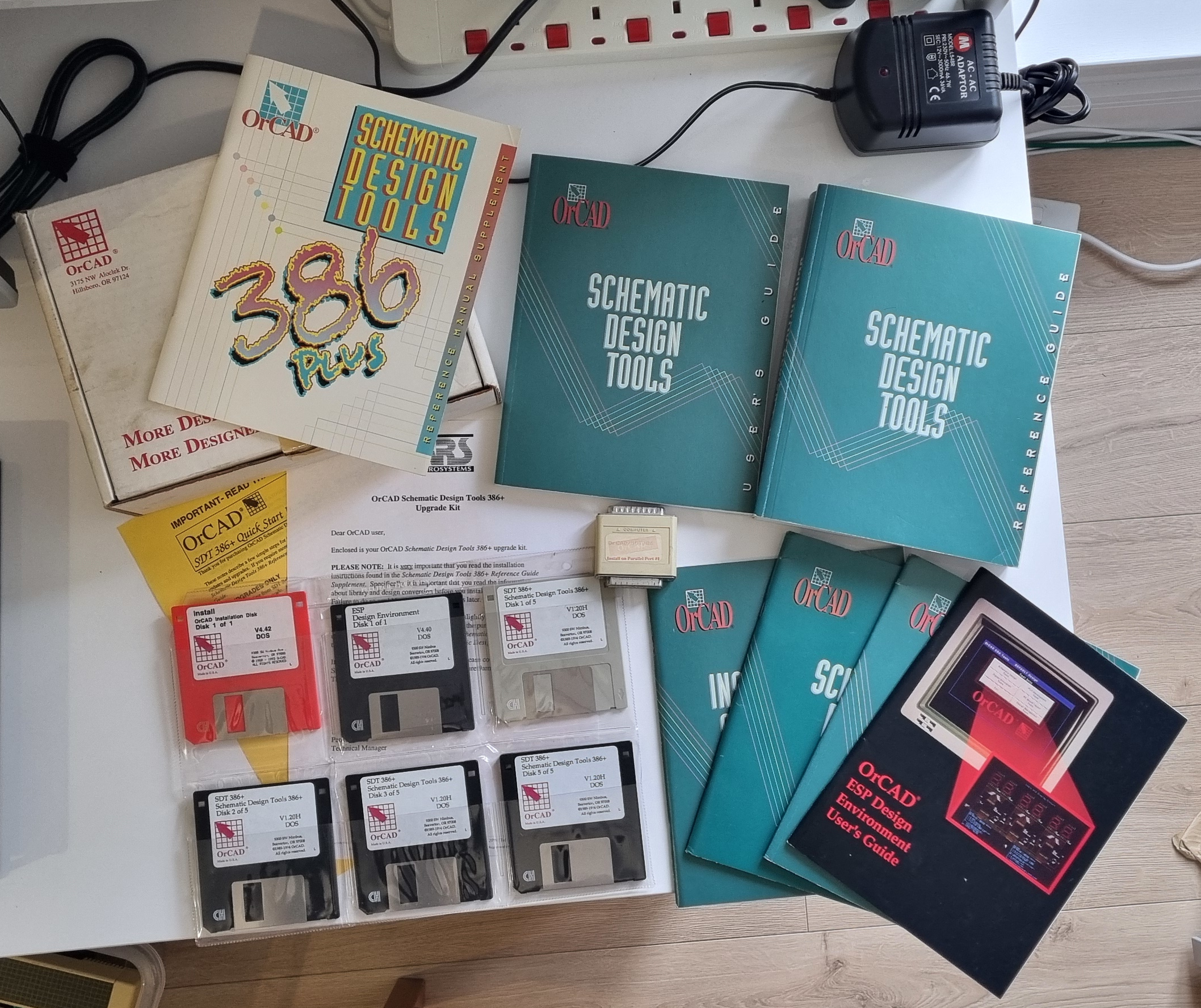
The Orcad 4.42 Upgrade pack.
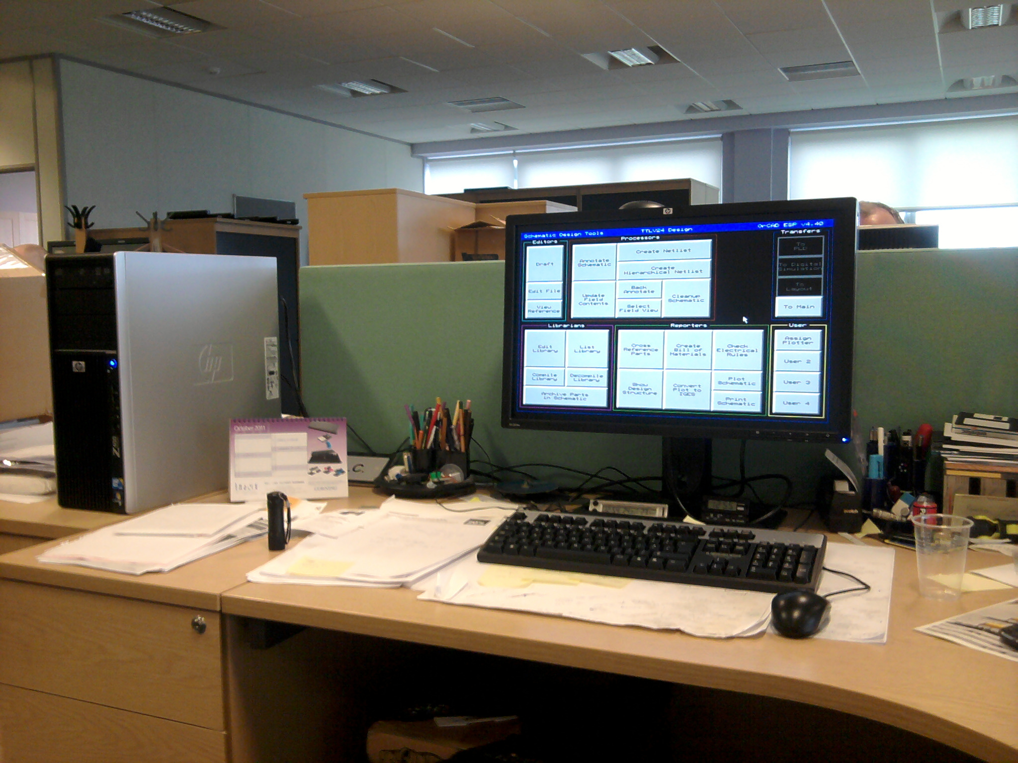
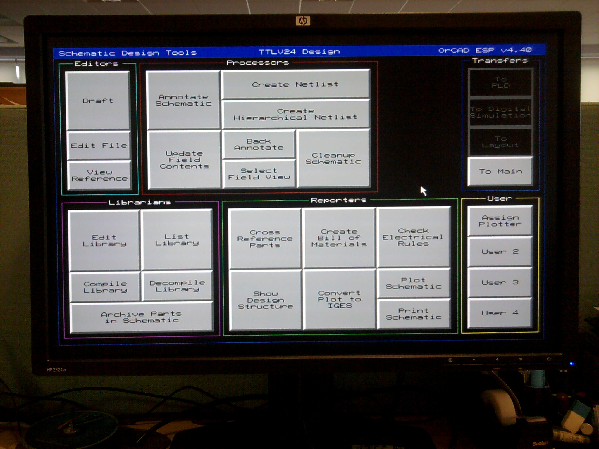
Installed on a 2011 PC (just to see if it would still work) and it was so much faster than a 486..I managed to get it connected to the office colour photocopier/printer.
Pen plotted on the HP plotter.
As circuits were re-used in different projects some of the paper versions were migrated to Orcad enabling easier PCB design as Net Lists could be produced and sent to contractors to convert to PCB layouts.
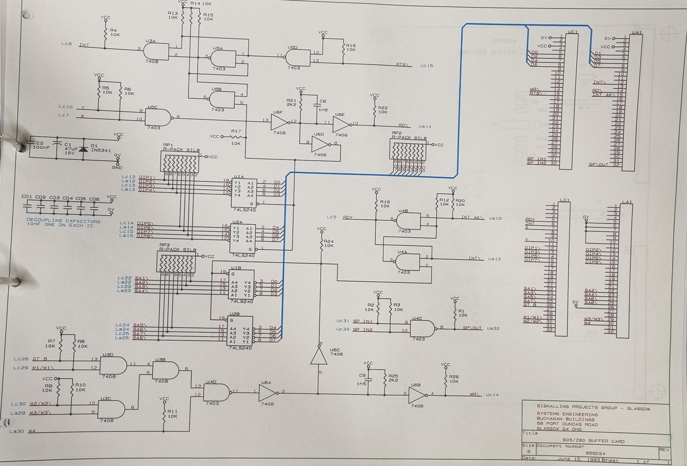
The EasyEDA Standard Edition produced drawings in a very similar way to Orcad so it wasn't such a great leap to get familiar with and use. Over the last 10 years I have produced well over one hundred projects with it and it was only last year when the Electron Clone (Ultra) moved to version 2.2 I had to look to the Pro version to complete it. It was getting too complex for the standard version to cope with.
The migration seemed quite smooth at first but I soon found out I had quite a lot of corrections to do. On further inspection most of the logic gate symbols had the power pins visible and shown on each gate. Only one set is necessary not six. The other connections that changed were the handling of connected potentials such as 0V and Ground, previously you just showed them connected with a wire but as far as I can see in the Pro version, although allowed, throws up an error.
I am now going through the process of migrating all 116 projects to the Pro version and here is an example of how a Logic gate comes accross.
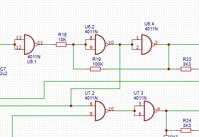
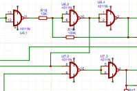
Before and after.
Power supply pins are shown on every gate from the same package! and sometimes they can intercept a wire and create a node where it shouldn't be. Every wire in every drawing has to be checked.
The Pro version favours entire package symbols instead of individual gates, which, while it can make it easier to put a new design together it is a lot of work to change older designs to make them compliant. It also makes new designs vitually impossible to read as you tend to use labels to connect gates rather than wires.
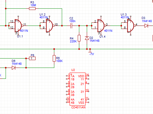
Transistor symbols didn't migrate unscathed either..
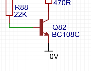
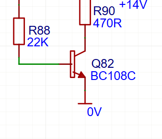
Before and after.
The PCB layouts faired a lot better, so far the only problem encountered is the copper area needs re-built but that is simple and quick to re-do.
The bigger problems will arise when an alteration is required to a circuit diagram and the PCB layout updated to that change - there will be massive changes inflicted on the PCB design as all the gates and power supplies will have been updated on the circuit design.
To make these changes to all one hundred and sixteen designs is not practical so I'll migrate all the designs to preserve them but I'll leave them as they are and only make changes if an update is required.