Electron Clone v2
The idea behind building v2 was to incorporate the MRB onto the pcb instead of it being a plug in board and to add an SD card reader for MMFS but as the title of this page says I'm not happy with the results. It took a bit of effort to find working parts and that includes the ULA, memory and a good 6502 but once found both versions v2.0 and v2.1 appeared to work normally. I say appear because I found that after being on for about 10 minutes this happens:
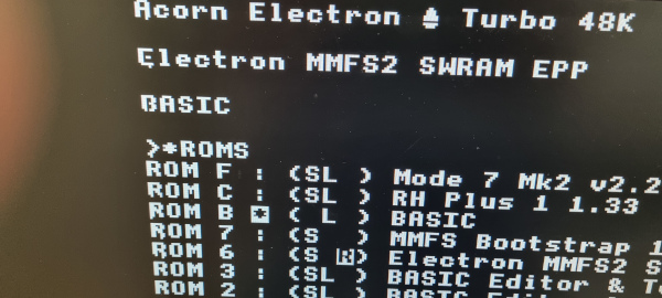
Occasionally some pixels will appear while others disappear! and it happens to both machines. Now these character distortions are stored in screen memory as they scroll up the screen when I issue commands. The new text is ok but over time it will be corrupted too.
I poured over the designs, comparing everything from V1.2, to v2.0 and v2.1. and the PCB tracking looking for some inconsistency but everything checks out ok. So what could I have done wrong?
Well my theory is that moving from a 2-layer board to a 4-layer was a big change and I hadn't considered the consequences. I must admit I didn't pay too much attention to this change, I only had it in my mind by adding power planes I would get a better distribution of power over the full PCB. It did indeed do that but I didn't look at the IC decoupling..I took it for granted that as long as the cappacitors were there they would do their job..I didn't give it a second thought.
Having looked over this part of the PCB layout I'd guess that about 95% of the decoupling capacitors wouldn't be doing their job..shockingly bad layout!! I have gone over each one and corrected their positions and ensured the tracking is as short as possible to each IC.
I am going to give this layout one more build so V2.2 is in the works. I have also fixed the keyboard connector error I introduced in V2.1 and I've moved the keyboard connectors 0.1" further back to help accomodate the keyboard ribbon cable when using the new slimmer case.
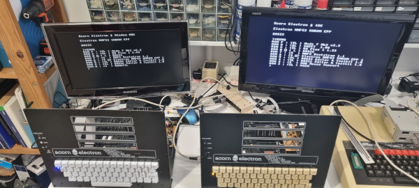
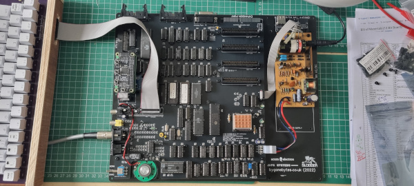
Clones under test..
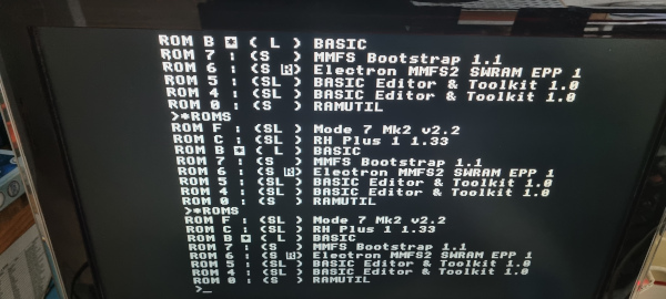
The corrupted characters scroll up..
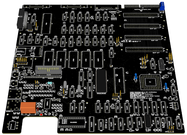
The new v2.2 board..looks the same as v2.1 but there's hundreds of tracking changes.
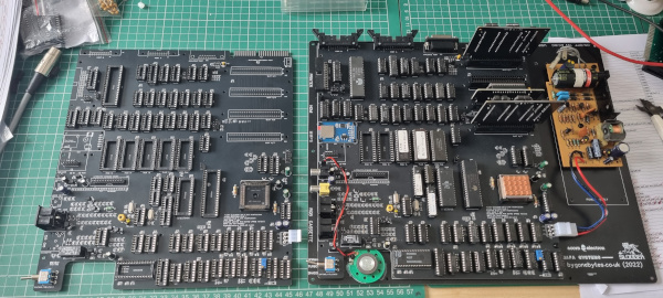
The PCB arrived and I've built it up ready to swap over the IC's. v2.2 on the left and v2.1 on the right.
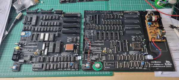
v2.2 has now been fitted to the base.
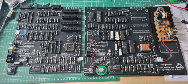
All the IC's swapped.
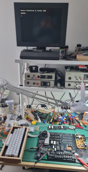
First switch on. Good that it worked first time. There was still a small issue with the characters - the same but different. On v2.0 and v2.1 after a few minutes the characters in the first column started to disform and got worse over time but on v2.2 only the first character in the top left of the screen would disform at switch on but would right itself after a few minutes. Once again I replaced the four memory chips and that has sorted it. I did one at a time and found the right hand chip fixed the issue - must be very slightly out of spec.
Now that it's all working OK I added all the connectors and the RGBtoHDMI board.
Then assembled it into a slimmer case. V2.0 (sitting next to it) is 5mm slimmer than v1.2 and v2.2 is 10mm slimmer.
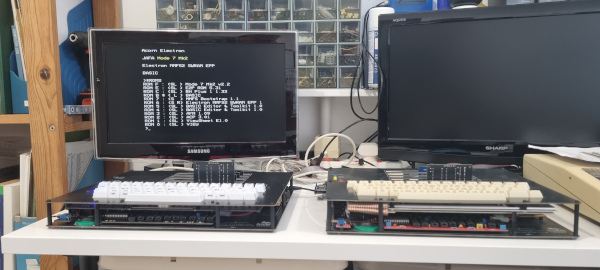
I tweaked the pot on the PCB to get the best possible symmetry for Mode 7.
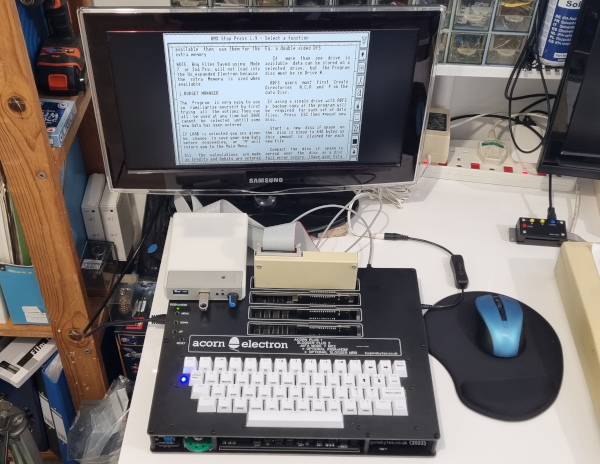
MMFS2 and the Slogger Stop Press ROMs don't get on together in the same system (another story to tell) so to use it I have to revert back to the Slogger Pegasus 400 and found a faulty 6522, it would work reading data out but not in so the mouse wouldn't work. A quick change and the mouse (and Stop Press) was working perfectly.
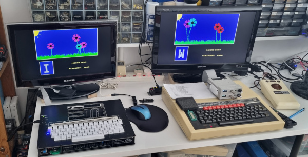
My BBC and Electron set up beside each other and I'd say the Electron looked and felt a bit sharper and snappier when running this Fun School disc.
Anyway I'm pleased that I can say version 2(.2) is now complete.